Vertical ring die pelleter

A granulator and ring die technology, applied in the direction of mold extrusion granulation, solid fuel, biofuel, etc., can solve the problems of affecting output and compression efficiency, increasing manufacturing difficulty and cost, and not being able to dissipate heat in time in the granulating chamber. To achieve the effect of improving service life, improving efficiency and easy maintenance

Pending Publication Date: 2018-07-06
JIANGSU YONGLI MACHINERY
View PDF0 Cites 4 Cited by
  • Summary
  • Abstract
  • Description
  • Claims
  • Application Information

AI Technical Summary

Problems solved by technology

[0004] ① Due to the arrangement of the ring die, the feed port of the ring die granulator must be placed sideways, and a thrust device is required to fill the ring die. Even so, it is still difficult for materials with light specific gravity to enter the pellet cavity;
[0005] ②The arrangement of the ring die causes the granulation chamber to not dissipate heat in time, which reduces the service life of the whole machine;
[0006] ③When the ring die rotates, the

Method used


Image

  • Vertical ring die pelleter
  • Vertical ring die pelleter
  • Vertical ring die pelleter

Examples


Embodiment 1

[0048] Embodiment one, such as Figure 1~4 , 6, 7, and 12,

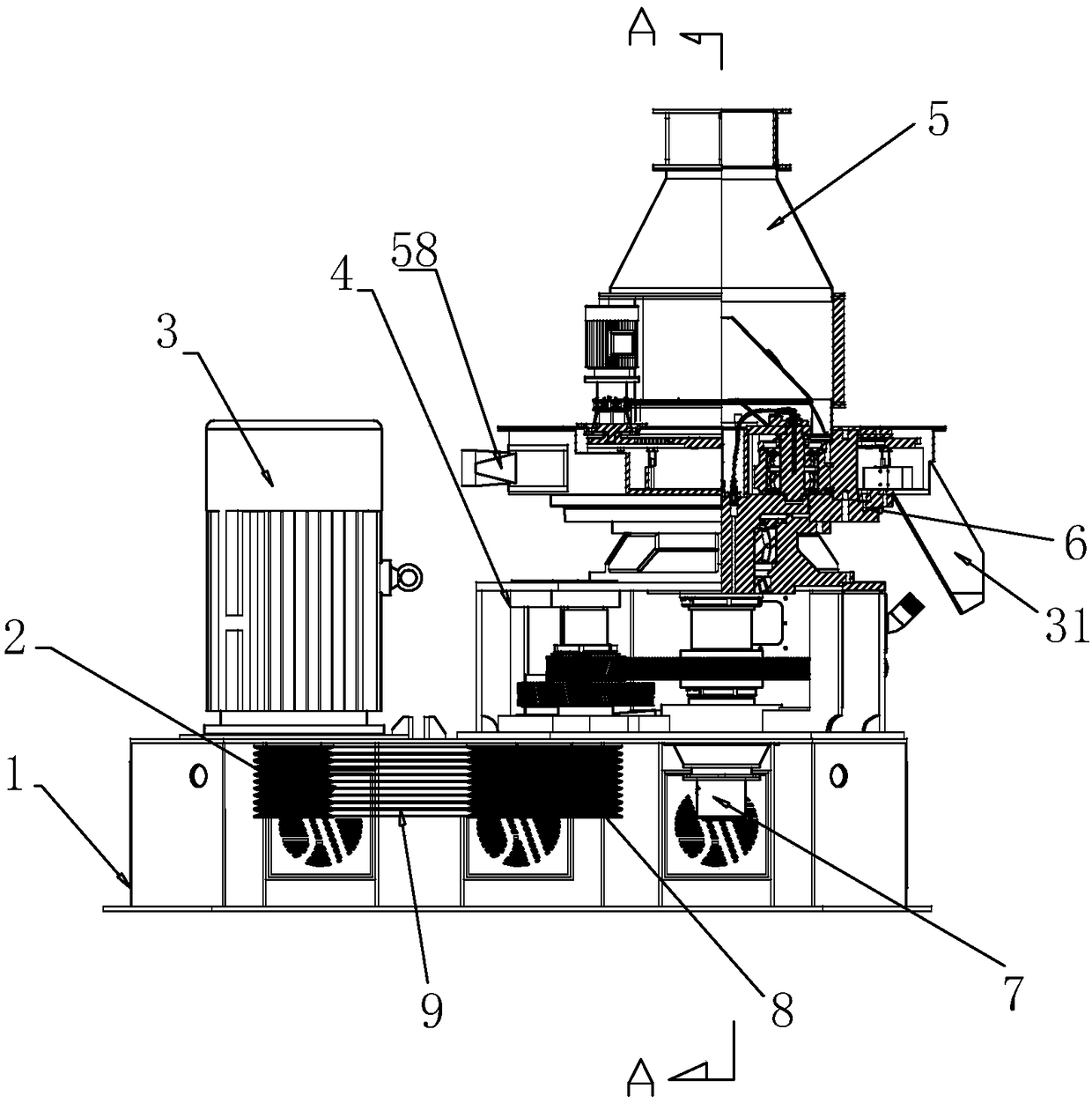
[0049] The vertical ring die granulator includes an organic base 1, a main motor 3, a reduction box 4, a main machine 6, a feeding cover 5, a reduction motor 17, a gear plate 22, a scraper 23 and a cutter 22-5, wherein:

[0050] --Such as figure 1 As shown, the main motor 3 is installed on one side of the frame, and the reduction box 4 is installed on the other side of the frame. , a belt 9 is wound between 1# belt pulley 2 and 2# belt pulley 8;

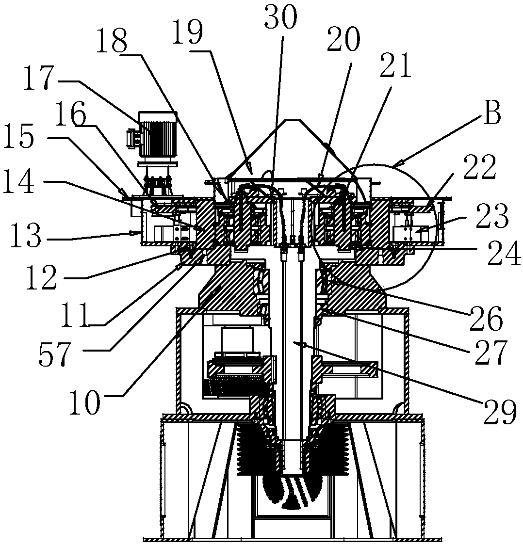
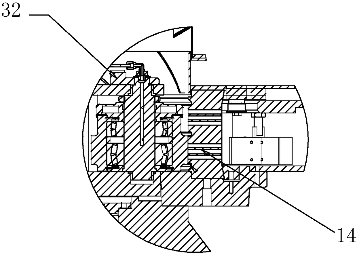
[0051] --Such as Figure 1~3 , 6, 7, and 12, the main engine includes a support 10, a ring mold base 11, a connecting base 18, a main engine shell 13, an upper cover 15, a ring mold 14, a pressure roller assembly 21 and a main shaft 29, and the support 10 is fixed On the reduction box 4, the ring die base 11 is fixed on the support 10, the ring die 14 is fixed on the ring die base 11, the connection base 18 is fixed on the ring die 14, and the feed cover 5 is fixed on t...

Embodiment 2

[0057] Such as figure 2 , 6 As shown, as an improvement of the present invention: the aforementioned main shaft and the reduction box are connected through 3# main shaft bearing 52; the main shaft and the support are connected through 1# main shaft bearing 26 and 2# main shaft bearing 27;

[0058] The aforementioned 1# main shaft bearing 26 and the 3 # main shaft bearing 52 are spherical roller bearings, and the aforementioned 2# main shaft bearing 27 is a tapered roller bearing.

Embodiment 3

[0059] Embodiment three, such as figure 1 , 2 , 6, 8, and 11,

[0060] As an improvement of the present invention:

[0061] There is a 1# lubricating grease pipeline in the middle of the aforementioned main shaft 29;

[0062] An oil separator 7 is also provided, and the oil separator 7 includes: an oil separator shaft 7-1, an oil separator bearing 7-2, a connecting flange 7-3, a seal 7-4, and an "O" ring 7-5, oil separator shell 7-6, oil separator end cap 7-8 and oil separator retaining ring 7-9; the aforementioned oil separator shaft 7-1 is installed on the oil separator through two oil separator bearings 7-2 Inside the oil separator shell 7-6; the fixed oil separator end cover 7-8 at one end of the aforementioned oil separator casing, the oil separator bearing 7-2 located on the side of the aforementioned oil separator end cover passes through the oil separator retaining ring 7 -9 limit; the other end of the aforementioned oil distribution pan shell is fixedly connected ...


PUM


Abstract

The invention relates to a vertical ring die pelleter, which comprises a main machine (6), wherein the main machine comprises a bracket (10), a ring die seat (11), a connection seat (18), a main machine shell (13), an upper cover (15), a ring die (14), a pressure roller assembly (21) and a main shaft (29), the main shaft (29) and the power output shaft of a speed reduction box share a shaft, the pressure roller assembly (21) is fixed on the upper portion of the main shaft, the ring die and the pressure roller assembly (21) are matched, the outer side of the ring die is provided with the main machine shell (13), the upper cover (15) is fixed on the main machine shell (13), a speed reduction motor (17) is fixed on the upper cover (15), a material scraping plate and a cutter are fixedly connected on a tooth disc (22), and the speed reduction motor drives the tooth disc to move. With the technical scheme of the present invention, the vertical ring die pelleter is reliable and safe.

Description

technical field [0001] The invention relates to a vertical ring die granulator, which is suitable for producing granules by using biomass materials with poor fluidity such as straw and paper scraps. The invention belongs to the technical field of ring die granulation. Background technique [0002] Renewable biofuels refer to high-density fuel rods or pellets formed by compressing agricultural and forestry wastes such as straw, sawdust, weeds, straw, shrub branches and even fruit shells and peels at room temperature or high temperature. The combustion value of this particle is 4 times higher than the combustion value of the traditional combustion method. It is a high-grade clean energy with a combustion method and calorific value close to coal but basically no pollutant emissions. It is used for urban and rural domestic energy and industrial use. It can provide an environmentally friendly, economical and safe green consumption method, and is a new energy advocated by the sta...

Claims


Application Information

Patent Timeline
IPC IPC(8): B01J2/22C10L5/44
CPCB01J2/22C10L5/442C10L5/445Y02E50/10Y02E50/30
Inventor 蒋立华尤兴锋
Owner JIANGSU YONGLI MACHINERY
Why Eureka
Try Eureka