Cooling device of implantable heart assisting blood pump

A technology of cardiac assistance and cooling device, applied in the field of medical devices, can solve the problems of thermal damage to surrounding tissues, temperature rise of artificial heart, etc., and achieve the effect of solving the problem of temperature rise, reducing heat radiation to the outside, and having a strong heat dissipation function.

Pending Publication Date: 2018-07-13
CHANGZHI JIUAN ARTIFICIAL HEART TECH DEV
View PDF12 Cites 7 Cited by
  • Summary
  • Abstract
  • Description
  • Claims
  • Application Information

AI Technical Summary

Problems solved by technology

The resistance of the coil itself will cause part of the energy to be dissipated in the form of heat, which will cause the temperature of the artificial heart to rise, which in turn will cause thermal damage to the surrounding tissue.

Method used


Image

  • Cooling device of implantable heart assisting blood pump
  • Cooling device of implantable heart assisting blood pump
  • Cooling device of implantable heart assisting blood pump

Examples


Embodiment 1

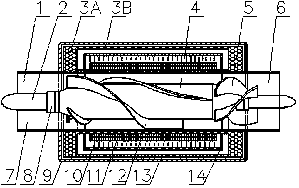
[0019] Such as figure 1 The cooling device shown is a "pump-machine combination" composed of a pump system and a drive motor system. The pump system is an axial flow pump system, including a pump barrel 1, a pump outlet 6, a pump inlet 7, a pump casing 9, and Installed shaft 2, bushing 8, impeller 4, impeller blade 12, tail guide vane 5 in the pump barrel; drive motor system includes stator: silicon steel sheet 11 and coil I10, rotor: impeller; silicon steel sheet 11 is installed in pump barrel 1 Outer circumference, the coil I10 is installed on the silicon steel sheet 11, and there is a cooling case 14 on the periphery of the stator; 3A is wider than 3B in order to increase the contact area between the directional heat conduction grid 3A and the pump cylinder 1, so that the heat generated by the stator can be conducted to the pump cylinder 1 as quickly as possible and taken away by the fast-flowing blood. The vacuum heat insulation component is a vacuum heat insulation layer...

Embodiment 2

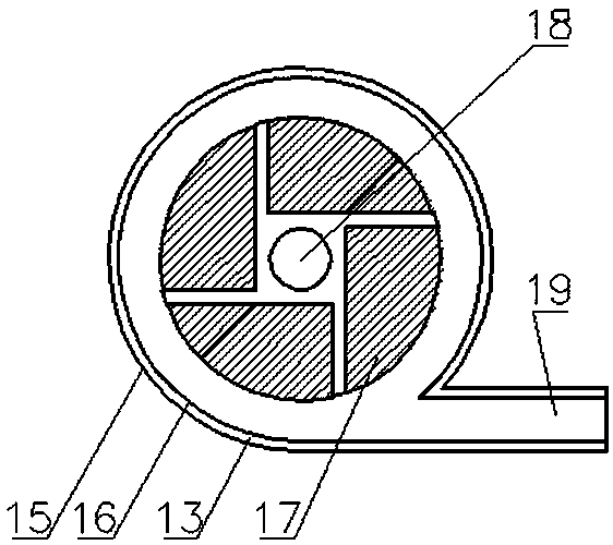
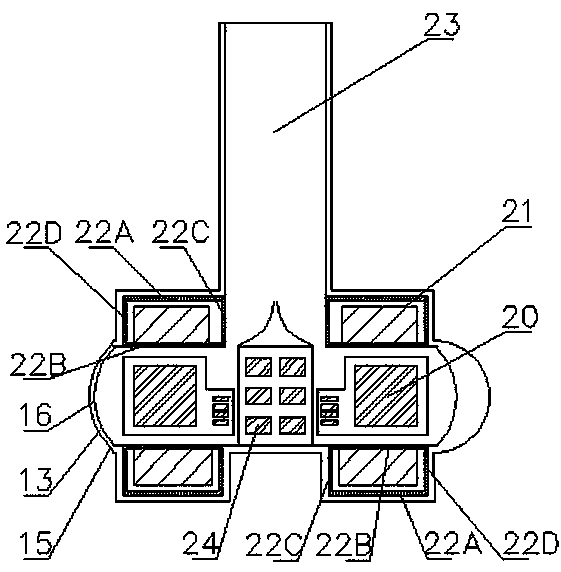
[0026] Such as figure 2 and image 3 As shown, the cooling device is a "pump-machine combination" composed of a pump system and a drive motor system. The pump system is a centrifugal pump system, including a centrifugal pump outer shell 15, a centrifugal pump inner shell 16, a centrifugal pump impeller 17, a Shaft 18, centrifugal pump outlet 19, magnet 20 in the impeller, centrifugal pump inlet 23, magnetic block 24 in the pump shaft; drive motor system includes stator: coil II 21, rotor: pump shaft 18 and centrifugal pump impeller 17; heat directional conduction parts The directional heat conduction grid 22 is located on the blood pump stator: the outer periphery of the coil II 21, respectively 22A, 22B, 22C, and 22D. The heat generated by a group of coils on the top is conducted to the surfaces 22B and 22C in contact with the blood flow as soon as possible through the 22A and 22D surfaces of the directional heat conduction grid, and is taken away by the fast-flowing blood....


PUM


Abstract

The invention relates to medical instruments, in particular to a cooling device of an implantable heart assisting blood pump. The cooling device comprises a pump system and a driving system. The pumpsystem is provided with the blood pump and a pump case, and the driving system is provided with a stator and a rotor. The cooling device is characterized by further comprising heat directional conducting parts and vacuum heat insulating parts; the heat directional conducting parts are located on the periphery of the stator of the blood pump, and the vacuum heat insulating parts are located in thepump case of the blood pump. The heat directional conducting parts directionally conduct heat generated by the stator of the blood pump into blood. Outward radiation of the heat is reduced through thevacuum heat insulating parts, temperature rise of the surface of the blood pump is reduced, and heat damage to tissue is avoided. Meanwhile, as the specific heat capacity of the blood is very large and the heat dissipation function of the surface of the human body is very strong, the heat cannot cause increase the temperature of the blood. Vacuum is formed between the vacuum heat insulating layers, so that outward radiation of the heat is reduced. The problem of temperature rise of an implantable artificial heart-heart ventricle assisting system is effectively solved, and the temperature riseis completely within the human body physiological range after the implantable blood pump is implanted in the body.

Description

technical field [0001] The invention relates to a medical device, in particular to a cooling device for an implanted cardiac auxiliary blood pump. Background technique [0002] Heart failure (heart failure) is a disease that seriously threatens human health. The most effective treatment for advanced heart failure is heart transplantation and artificial heart therapy. Due to the extreme shortage of heart transplant donors, which is far from meeting the needs of heart failure treatment, the market demand for artificial hearts continues to increase, so the research on artificial hearts has become a hot spot. Various artificial hearts have been researched. For example, patent CN104707194A is an implantable axial flow blood pump based on blood flow pressure and Pivot support, which uses a built-in coil as a stator to generate an alternating magnetic field to drive the impeller to rotate. Patent CN104436338A adopts self-suspension technology to manufacture self-suspension axial...

Claims


Application Information

Patent Timeline
Patent Type & Authority Applications(China)
IPC IPC(8): A61M1/10A61M1/12
CPCA61M2205/3606A61M2205/04A61M60/00A61M60/205A61M60/40A61M60/50A61M60/148
Inventor 沈喆陈海丰田步升祝会占
Owner CHANGZHI JIUAN ARTIFICIAL HEART TECH DEV
Why Eureka
Try Eureka