Carbonization cracking system for waste plastics

A cracking system and plastic technology, used in special forms of dry distillation, petroleum industry, preparation of liquid hydrocarbon mixtures, etc., can solve the problems of uneven heating, high energy consumption, insufficient raw material recycling rate, etc. The effect of temperature stabilization and energy reduction

Pending Publication Date: 2018-07-17
光大绿色环保技术服务江苏有限公司
0 Cites 7 Cited by

AI-Extracted Technical Summary

Problems solved by technology

The pyrolysis furnace adopts independent burner heating or electric heating. This heating method consumes a lot of energy and has the problem of uneven heatin...

Method used

As shown in Figure 1, on cracking furnace 2, also be provided with air pressure sensor 14, air pressure sensor 14 is positioned at cracking chamber, and air pressure sensor 14 is electrically connected with the controller of booster fan 7, and in cracking process, air pressure sensor 14 Detect the oil and gas pressure in the cracking chamber, and feed back the detection results to the controller of the booster fan 7, and the controller of the booster fan 7 controls the speed of the booster fan 7 according to the feedback results, thereby controlling the air flow of the oil and gas pipeline , to realize the dynamic adjustment of the air pressure in the cracking chamber, so that the air pressure in the cracking process can be maintained in the range of micro-negative pressure -100 ~ -300pa, to avoid oil and gas leakage due to excessive air pressure in the cracking furnace 2, and to achieve zero leakage in the production process .
In the ...

Abstract

The invention discloses a carbonization cracking system for waste plastics. The system utilizes a molten salt furnace to provide heating heat for a cracking furnace, so that a material in the crackingfurnace is continuously cracked, and a combustible gas generated by cracking of the material is used as a fuel of the molten salt furnace to maintain continuous heating of the molten salt by the molten salt furnace; the molten salt circularly flows in the cracking furnace and the molten salt furnace, so that a cracking chamber is heated continuously; and because a specific heat capacity of the molten salt is larger, the molten salt has a temperature of about 500 DEG C when flowing out from the molten salt furnace, and the molten salt has a temperature of about 480 DEG C when flowing back to the molten salt furnace, a cracking temperature difference is only about 20 DEG C, so that the entire carbonization cracking process is performed in a very stable temperature range. According to the system provided by the invention, in the above way, firstly, the material can be fully cracked; and secondly, the combustible gas generated by cracking is directly utilized, so that the molten salt furnace does not need to consume an external combustible gas, energy consumption of the carbonization cracking system is reduced, and a utilization rate of the material is improved.

Application Domain

ProductsReagents +4

Technology Topic

Energy consumptionSpecific heat +5

Image

  • Carbonization cracking system for waste plastics

Examples

  • Experimental program(1)
  • Effect test(1)

Example Embodiment

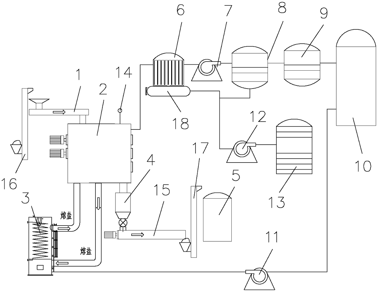
[0016] refer to figure 1 , a waste plastic carbonization cracking system, including a cracking furnace 2 and a molten salt furnace 3, the cracking furnace 2 has an inner shell and an outer shell, the inside of the inner shell is a cracking chamber, a sealed cavity is formed between the inner shell and the outer shell, and the molten salt furnace The molten salt outlet and the molten salt inlet of 3 are all communicated with the sealed cavity through pipelines, and the inner shell of cracking furnace 2 has raw material inlet, carbon black outlet and oil gas outlet, and the raw material inlet of cracking furnace 2 is provided with sealed feeder 1, in The carbon black outlet of the cracking furnace 2 is provided with a sealed discharger 4, and the system also includes an oil-gas condenser 6, a booster fan 7, an oil-gas separation tank 8, a desulfurization tower 9 and a gas tank 10 connected in sequence through pipelines, and the cracking furnace 2 The oil and gas outlet of the gas tank is connected to the inlet of the oil and gas condenser 6, and the gas tank 10 is connected to the combustion chamber of the molten salt furnace 3 through a gas pipeline, and the gas pipeline for blowing the gas in the gas tank 10 into the molten salt furnace 3 The fan 11, the oil outlet of the oil-gas condenser 6 and the oil-gas separation tank 8 are connected to the oil tank 13 after passing through the oil pump 12.
[0017] The working principle of the carbonization cracking system is: crush tires, plastics and other raw materials into 20mm granular materials, and transport the materials to the sealing feeder 1, and the sealing feeder 1 realizes uninterrupted discharge by material extrusion and at the same time realizes sealing The effect of adding an appropriate amount of additives in the cracking furnace 2, after the material is sent into the cracking furnace 2, cracking begins under the effect of high temperature in the cracking furnace 2, and the heating temperature of the cracking furnace 2 is between 450-500 ° C. During the reaction process, the material is converted into hydrocarbon gas and coke, and the hydrocarbon gas is transported from the oil-gas outlet pipe to the oil-gas condenser 6, and the oil-gas condenser 6 fractionates the hydrocarbon gas into cracked oil and combustible gas. The pyrolysis oil flows out from the oil outlet of the oil-gas condenser 6 and is pumped into the oil tank 13 by the oil pump 12; while the combustible gas flows out from the gas outlet of the oil-gas condenser 6 and is blown into the oil-gas separation tank 8 by the booster fan 7, and the oil and gas The separation tank 8 separates some unseparated suspended oil and gas, and the separated oil and gas flow out from the oil outlet of the oil and gas separation tank 8 and are pumped into the oil tank 13 by the oil pump 12, while the combustible gas is discharged from the oil and gas separation tank 8 The gas outlet flows out and flows into the desulfurization tower 9, and clean combustible gas is obtained after the action of the desulfurization tower 9, and the clean combustible gas is sent into the gas tank 10; coke is discharged from the carbon black outlet of the cracking furnace 2 and enters the sealed The discharger 4 sends the coke into the container through the sealed discharger 4, and the sealed discharger 4 realizes the sealed discharge through the material level.
[0018] During the working process, the gas blower 11 continuously sends the combustible gas in the gas tank 10 into the combustion chamber of the molten salt furnace 3 to maintain continuous heating of the molten salt by the molten salt furnace 3 . The molten salt circulates between the sealed chamber and the molten salt furnace 3, thereby continuously heating the cracking chamber. Due to the large specific heat capacity of the molten salt, the temperature of the molten salt flowing out of the molten salt furnace 3 is about 500 degrees, while When the molten salt reflows to the molten salt furnace 3, its temperature is about 480 degrees, and the cracking temperature difference is only about 20 degrees. The small temperature difference allows the molten salt to be quickly heated to 500 degrees again. When the molten salt furnace 3 flows out, it can always maintain a temperature of about 500 degrees to ensure that the heating temperature in the cracking chamber is very stable, and the temperature of the cracking chamber varies very little, so that the entire carbonization and cracking process can be carried out in a very stable temperature range. , so that the material is continuously and stably cracked. The benefits brought by this are: first, it can ensure that the material is fully cracked; second, it directly uses the combustible gas produced by cracking, so that the molten salt furnace 3 does not need to consume external combustible gas, which reduces the energy consumption of the carbonization cracking system, that is, increases Utilization of materials.

PUM

no PUM

Description & Claims & Application Information

We can also present the details of the Description, Claims and Application information to help users get a comprehensive understanding of the technical details of the patent, such as background art, summary of invention, brief description of drawings, description of embodiments, and other original content. On the other hand, users can also determine the specific scope of protection of the technology through the list of claims; as well as understand the changes in the life cycle of the technology with the presentation of the patent timeline. Login to view more.

Similar technology patents

Paint used for coiled metal material

Owner:ZHEJIANG TRANSFER PAINT CO LTD

Linear fiction welding device

InactiveCN101559532Aconvenient choiceReduce energy consumption
Owner:BEIJING AVIATION MFG ENG INST CHINA AVIATION NO 1 GRP

Virtual thermostat for a zonal temperature control

InactiveUS9644857B1reduce energy consumptionimprove thermal comfort
Owner:ASHGRIZ NASSER +1

Classification and recommendation of technical efficacy words

  • Reduce energy consumption

Preparation method of high-strength hydrogel

InactiveCN103739861AThe preparation process takes a short timeReduce energy consumption
Owner:HENAN POLYTECHNIC UNIV

Catalyst for gas phase hydrogenation of acetic acid to prepare ethanol

Owner:DALIAN INST OF CHEM PHYSICS CHINESE ACAD OF SCI +1

Wireless emergency lighting system

ActiveUS8491159B2ease of installationreduce energy consumption
Owner:RING LLC
Why Eureka
Try Eureka