Gregorian antenna based on super surface

A Gregorian and metasurface technology, applied to antennas, antenna grounding switch structural connections, electrical components, etc., can solve problems such as large phase compensation errors, complexity, and increased phase compensation errors, and achieve accurate wavefront calibration and optimization Radiation characteristics, effects of precise phase compensation

Active Publication Date: 2018-07-20
XIDIAN UNIV
View PDF3 Cites 3 Cited by
  • Summary
  • Abstract
  • Description
  • Claims
  • Application Information

AI Technical Summary

Problems solved by technology

The reflective surface of a typical Gregorian antenna is composed of a metal surface processed into a curved profile. Although the design is simple, it requires high processing requirements.
[0003] In order to solve the problem of inconvenient processing and assembly of curved reflective surfaces designed to regulate electromagnetic waves, existing research uses metamaterials to regulate electromagnetic waves, and realizes planar Gregorian antennas by printing microstrip plates.
Such as the Chinese patent, the application publication number is CN 102800995 A, the invention titled "a Cassegrain type metamaterial antenna" discloses a Cassegrain type metamaterial antenna, the invention passes through the middle of the ground dielectric plate A planar snowflake-like cross-shaped metal microstructure is set, and the metal reflective surface is covered with a metamaterial with a gradient change in refractive index to approximate the reflection characteristics of a curved reflector, and a Gregorian antenna with a flat plate structure is realized, but its phase compensation method is electromagnetic wave successively. After passing through the metamaterial twice, the wavefront is calibrated by using the different constitutive parameters of the metamaterial on the propagation path to change the ...

Method used


Image

  • Gregorian antenna based on super surface
  • Gregorian antenna based on super surface
  • Gregorian antenna based on super surface

Examples


Embodiment Construction

[0029] The present invention will be further described below in conjunction with the accompanying drawings and specific embodiments.

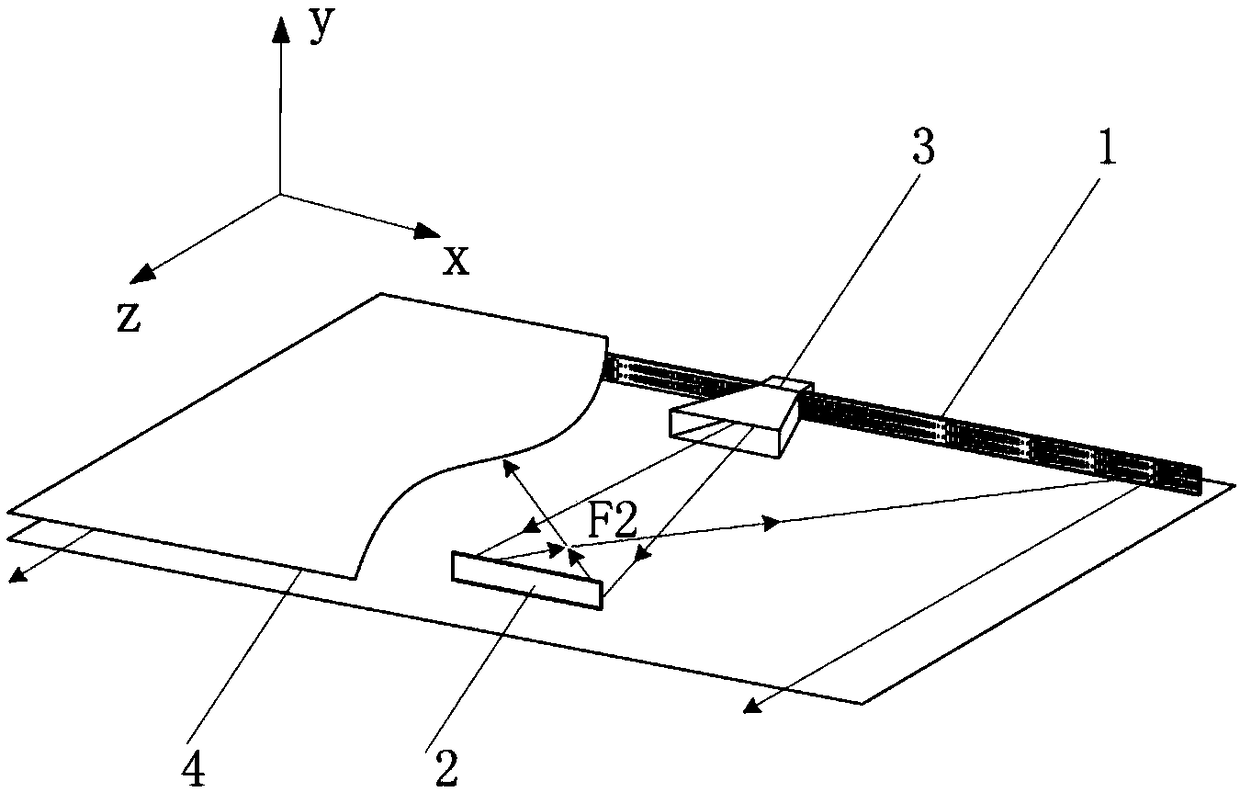
[0030] refer to figure 1 , the present invention includes a primary reflector 1, a secondary reflector 2, a feed source 3 and a slab waveguide 4, and the primary reflector 1, the secondary reflector 2 and the feed source 3 are clamped between two metal plates of the slab waveguide 4 . The setting of main reflector 1 and sub-reflector 2 adopts the feed-forward method, the main reflector 1 and sub-reflector 2 are arranged in parallel, the feed source 3 is located at the disconnected position of the midpoint of the main reflector 1, and the feed source 3 adopts an H-surface rectangular horn Structure, the slab waveguide 4 is composed of two rectangular metal plates of the same size, which is used to confine the uncompleted phase-compensated electromagnetic wave between the two metal plates of the slab waveguide, and the cylindrical wave emitted b...


PUM


Abstract

The invention provides a Gregorian antenna based on a super surface, and aims to reduce the phase compensation error of the antenna and simplify the antenna structure at the same time. The Gregorian antenna comprises a slab waveguide, a main reflector, an auxiliary reflector and a feed source, wherein the main reflector, the auxiliary reflector and the feed source are clamped between two metal plates of the slab waveguide, both the main reflector and the auxiliary reflector adopt a phase sudden change super surface structure constructed based on a generalized Snell's law, the size of a metal ring microstructure on a phase control layer of the main reflector is decided by the electromagnetic wave incident angle and the scattering parameter phase at the location so as to realize an electromagnetic wave phase compensation characteristic similar to that of a paraboloid, the size of a metal ring microstructure on a phase control layer of the auxiliary reflector is decided by the electromagnetic wave incident angle and the scattering parameter phase at the location so as to realize an electromagnetic wave phase compensation characteristic similar to that of an ellipsoid; and the feed source is located at the midpoint of the main reflector which is opposite to the phase control layer of the auxiliary reflector, a near focus of the auxiliary reflector is overlapped with a focus of themain reflector, and a far focus of the auxiliary reflector is overlapped with a phase center of the feed source.

Description

technical field [0001] The invention belongs to the technical field of antennas, and relates to a Gregorian antenna, in particular to a Gregorian antenna with a planar structure realized by a phase mutation metasurface based on generalized Snell's theorem, which can be used in the microwave field. technical background [0002] The microwave reflector antenna is mainly a parabolic antenna, which uses the collimation effect of the parabolic reflector to form a highly directional radiation pattern. The Gregorian antenna adds an elliptical sub-reflector on the basis of the parabolic antenna. Electromagnetic waves pass through the sub-reflector and are reflected by the main reflector to form a highly directional radiation pattern. Compared with ordinary parabolic antennas, on the one hand, the added sub-reflector is easier to design the surface field distribution and can optimize the radiation performance of the antenna; on the other hand, since the feed source is placed close to...

Claims


Application Information

Patent Timeline
IPC IPC(8): H01Q15/14H01Q19/185H01Q1/50
CPCH01Q1/50H01Q15/14H01Q19/185
Inventor 杨锐李冬张澳芳高东兴杨佩雷振亚
Owner XIDIAN UNIV
Why Eureka
Try Eureka