
Film for transparent conductive layer lamination, method for producing same, and transparent conductive film

A technology of transparent conductive film and transparent conductive layer, which is applied in cable/conductor manufacturing, conductive layer on insulating carrier, semiconductor/solid-state device manufacturing, etc. It can solve problems such as defects, reduced device life, and reduced device characteristics, and achieve smoothness Excellent performance, low surface resistivity, and high heat resistance

Inactive Publication Date: 2018-07-31
LINTEC CORP
View PDF6 Cites 1 Cited by
  • Summary
  • Abstract
  • Description
  • Claims
  • Application Information

AI Technical Summary

Problems solved by technology

[0003] In the above-mentioned structure, for example, when a transparent conductive layer is stacked on the auxiliary electrode layer, a height difference corresponding to the thickness of the auxiliary electrode layer will occur, and this height difference will affect the active layer ( Drive layer, etc.) are also affected by conductive parts, and become the main cause of deterioration of device characteristics, defects caused by short circuits, etc., and reduction of device life

Method used

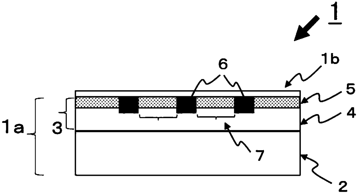
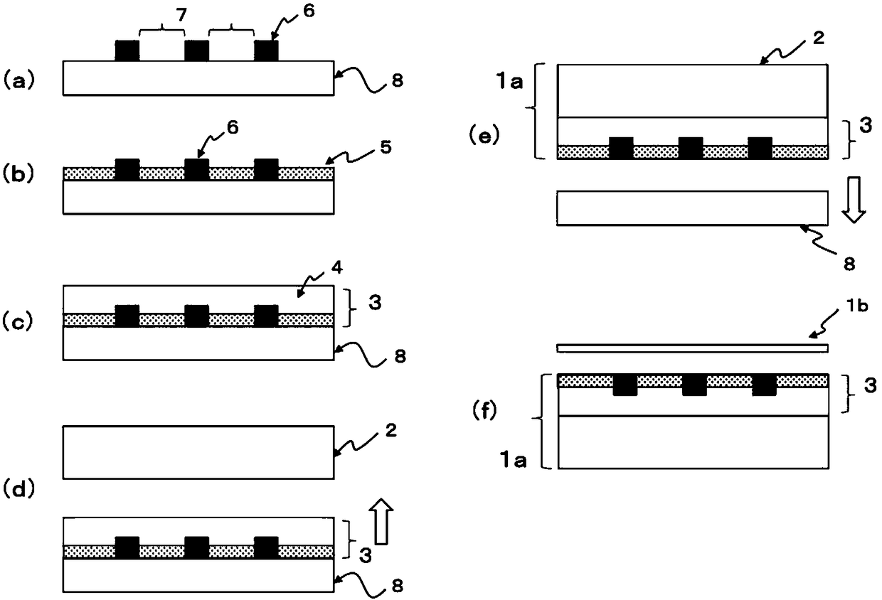
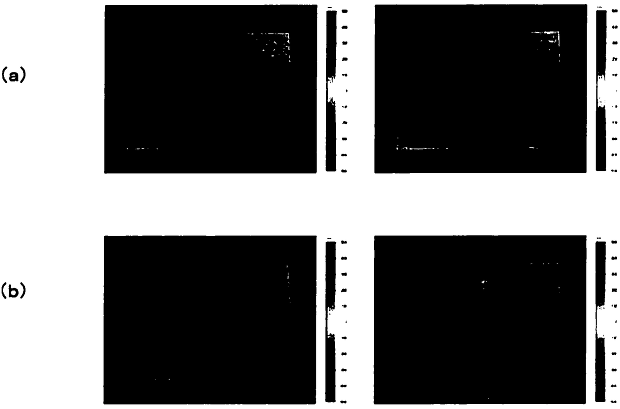

Image

  • Film for transparent conductive layer lamination, method for producing same, and transparent conductive film
  • Film for transparent conductive layer lamination, method for producing same, and transparent conductive film
  • Film for transparent conductive layer lamination, method for producing same, and transparent conductive film

Examples


Embodiment 1

[0191] Conductive paste (manufactured by Mitsuboshi Belting, product name: EC-264) was printed on a transfer substrate (manufactured by Lintec Corporation, product name: MT-320TV) using a screen printing device (manufactured by Micro Tech Corporation, name: PLD8030) and heat-dried to form an auxiliary electrode layer consisting of a grid-shaped metal thin line pattern with a thickness of 6 μm, a line width of 50 μm, and a pitch of 2000 μm.

[0192] Next, the transparent resin layer B containing inorganic fine particles, that is, the acrylic resin composition A as the heat-resistant layer is applied by bar coating. *1 (manufactured by JSR Corporation, product name: OPSTAR Z7530), a heat-resistant layer is provided on the opening of the auxiliary electrode layer, and an acrylic resin composition B as the transparent resin layer A is further coated by bar coating *2 (manufactured by Toagosei Co., Ltd., product name: UVX-6125), a transparent resin layer A was provided on the auxil...

Embodiment 2

[0224] In Example 1, except having changed the thickness of a heat-resistant layer into 4 micrometers, it carried out similarly to Example 1, and produced the film for transparent conductive layer laminations, and a transparent conductive film. The arithmetic mean roughness Ra of the composite layer side surface of the produced transparent conductive layer laminate film and the transparent conductive layer side surface of the transparent conductive film, and the surface resistivity of the transparent conductive film were evaluated. The results are shown in Table 1.

Embodiment 3

[0226] In Example 1, except having changed the thickness of a heat-resistant layer into 19 micrometers, it carried out similarly to Example 1, and produced the film for transparent conductive layer laminations, and a transparent conductive film. The arithmetic mean roughness Ra of the composite layer side surface of the produced transparent conductive layer laminate film and the transparent conductive layer side surface of the transparent conductive film, and the surface resistivity of the transparent conductive film were evaluated. The results are shown in Table 1.


PUM

PropertyMeasurementUnit
Thicknessaaaaaaaaaa
Particle sizeaaaaaaaaaa
Arithmetic mean roughnessaaaaaaaaaa

Abstract

The present invention provides a film for transparent conductive layer lamination, which has high heat resistance and excellent smoothness of the surface including an auxiliary electrode layer; a method for producing this film for transparent conductive layer lamination; and a transparent conductive film which suppresses decrease of device service life and the occurrence of a device characteristicdefect due to a short circuit between electrodes within a device, while having low surface resistivity. A film for transparent conductive layer lamination, which is obtained by laminating, as a composite layer on a transparent resin film base, at least a transparent resin layer A, a metal layer having an opening and a transparent resin layer B arranged in the opening and containing inorganic fineparticles, and wherein a surface of the composite layer, said surface being on the reverse side of the transparent resin film base-side surface, is composed of the metal layer and the transparent resin layer containing inorganic fine particles; a method for producing this film for transparent conductive layer lamination; and a transparent conductive film using this film for transparent conductivelayer lamination.

Description

technical field [0001] The present invention relates to a film for a transparent conductive layer laminate, a method for producing the same, and a transparent conductive film. Background technique [0002] In recent years, along with the development of printed electronic devices, the increase in area and flexibility of electronic devices mainly using organic materials, such as organic thin-film solar cells and organic EL lighting, which are expected to spread in the future, are being promoted. From the viewpoint of making high-performance and large-area electronic devices, for the transparent conductive film used as a light-transmitting electrode in these electronic devices, in order to improve the performance of the transparent conductive layer when the device is working (collecting electricity or applying voltage), In general, power loss and characteristic distribution due to high resistivity require lower resistance of the surface of the transparent conductive layer. To ...

Claims


Application Information

Patent Timeline
IPC IPC(8): B32B15/08H05B33/10H05B33/26H05B33/28H01B5/14H01B13/00H01L51/44H01L51/50
CPCB32B15/08H01B5/14H05B33/28Y02E10/549H05B33/22Y02P70/50H10K30/80H10K30/50H10K30/82H10K50/80B32B27/08B32B27/20B32B37/025B32B37/26H01B13/0026H01B13/0036H05B33/26B32B2255/10B32B2255/205B32B2307/412
Inventor 森田亘原务武藤豪志近藤健
Owner LINTEC CORP
Learn More