
Manufacturing method of TFT array substrate and TFT array substrate

A technology of an array substrate and a manufacturing method, which is applied in the display field, can solve the problems affecting the carrier mobility of a polysilicon layer, the starting point and direction are disordered and disordered, and there are many grain boundaries between crystal grains, so as to improve the carrier mobility, The effect of low number of grain boundaries and high carrier mobility

Inactive Publication Date: 2018-10-09
TCL CHINA STAR OPTOELECTRONICS TECH CO LTD
View PDF3 Cites 1 Cited by
  • Summary
  • Abstract
  • Description
  • Claims
  • Application Information

AI Technical Summary

Problems solved by technology

When the existing excimer laser annealing method is used to produce low-temperature polysilicon, a buffer layer is generally formed on the substrate first, and then an amorphous silicon layer is formed on the buffer layer, and then the amorphous silicon layer is dehydrogenated at high temperature. , and then use excimer laser annealing equipment to scan the amorphous silicon layer with laser. The amorphous silicon layer receives the energy of the laser and heats up, then recrystallizes to form a polysilicon layer. During the recrystallization process, the direction of crystallization is from low energy to high The direction of energy, that is, the direction from low temperature to high temperature, so the starting point and direction of crystallization in the existing amorphous silicon layer are disordered, resulting in the recrystallization of the polysilicon layer, the grain size is too small, the crystallization There are more grain boundaries between grains, which affect the carrier mobility of the polysilicon layer

Method used


Image

  • Manufacturing method of TFT array substrate and TFT array substrate
  • Manufacturing method of TFT array substrate and TFT array substrate
  • Manufacturing method of TFT array substrate and TFT array substrate

Examples


no. 1 example

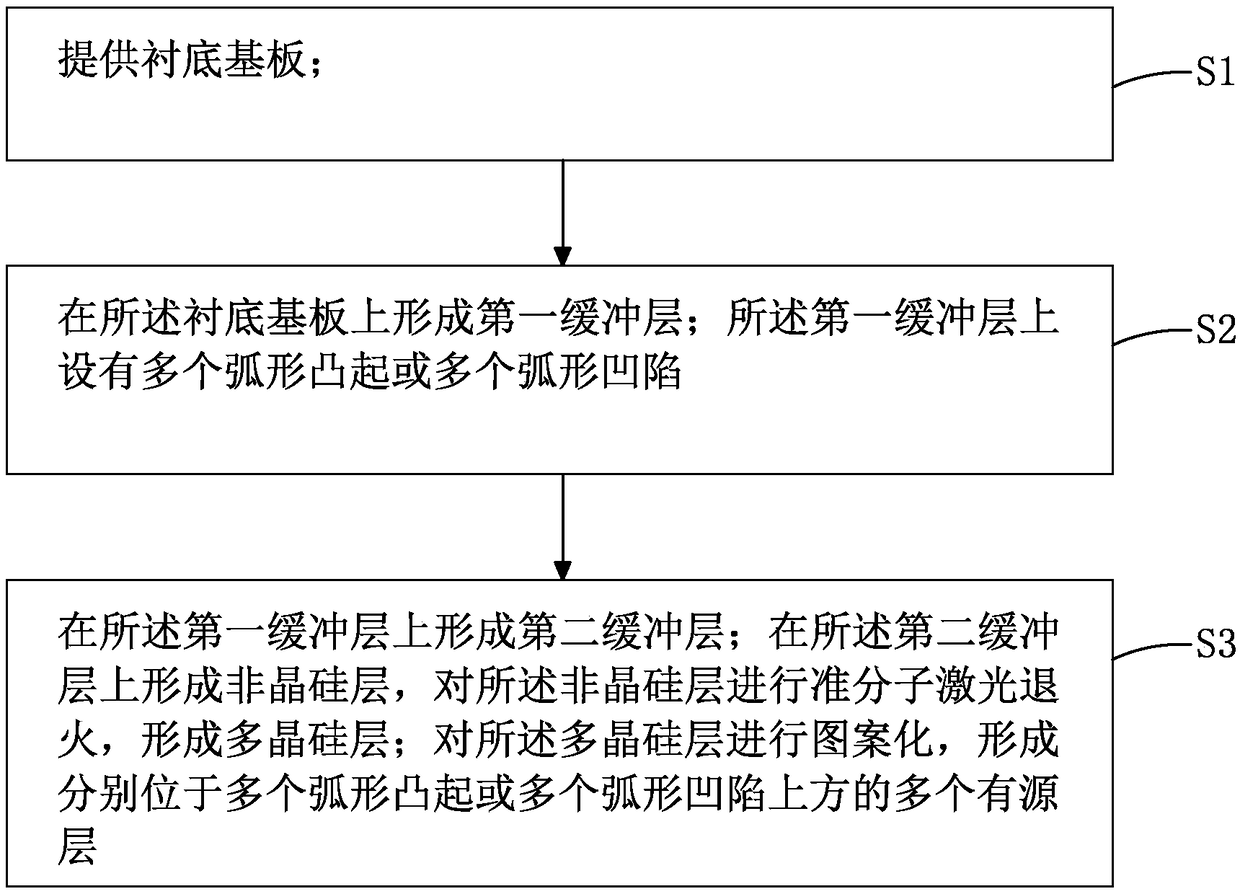
[0044] see figure 1 , and combined with Figure 2 to Figure 11 , the first embodiment of the manufacturing method of the TFT array substrate of the present invention comprises the following steps:

[0045] Step S1, please refer to figure 2 , providing a base substrate 10 .

[0046] Specifically, the material of the base substrate 10 may be glass or a flexible material.

[0047] Step S2, please refer to Figure 6 , forming a first buffer layer 20 on the base substrate 10 . The first buffer layer 20 is provided with a plurality of arc-shaped protrusions 21 .

[0048] Specifically, the material of the first buffer layer 20 is silicon nitride (SiNx), silicon oxide (SiOx) or other materials commonly used in buffer layers in TFT array substrates.

[0049] Specifically, the thickness of the first buffer layer 20 is preferably

[0050] Specifically, in the first embodiment of the present invention, the first buffer layer 20 with a plurality of arc-shaped protrusions 21 is fo...


PUM


Abstract

The invention provides a manufacturing method of a TFT array substrate and the TFT array substrate. The manufacturing method of the TFT array substrate comprises the following steps: forming a first buffer layer on a substrate, wherein multiple arc bulges or multiple arc canyons are arranged on the first buffer layer; and then forming an amorphous silicon layer on a second buffer layer formed on the first buffer layer, wherein the arc bulges or the arc canyons can change the light path of the large irradiating the amorphous silicon layer in the process of performing excimer laser annealing onthe amorphous silicon layer to form the poly-crystalline silicon layer, thereby forming energy gradient in the amorphous silicon layer. The crystallite dimension in the formed poly-crystalline siliconlayer is increased, the crystal boundary number is reduced, the carrier migration rate of the TFT device is improved, and the electricity of the TFT device is promoted.

Description

technical field [0001] The invention relates to the field of display technology, in particular to a manufacturing method of a TFT array substrate and the TFT array substrate. Background technique [0002] In the field of display technology, flat panel display devices such as Liquid Crystal Display (LCD) and Organic Light-Emitting Diode (OLED) displays have gradually replaced Cathode Ray Tube (CRT) display devices. The liquid crystal display device has many advantages such as a thin body, power saving, and no radiation, and has been widely used. [0003] Existing display devices are generally provided with a thin film transistor (Thin Film Transistor, TFT) array substrate as a driving structure, and the TFT array substrate includes a plurality of TFT devices arranged in an array. The performance of the TFT array substrate greatly affects the quality of the display device. With the continuous development of flat panel display technology, display devices with high resolution ...

Claims


Application Information

Patent Timeline
Patent Type & Authority Applications(China)
IPC IPC(8): H01L27/12H01L21/268H01L21/77
CPCH01L21/268H01L27/1222H01L27/1285H01L27/1288
Inventor 张瑞军王松
Owner TCL CHINA STAR OPTOELECTRONICS TECH CO LTD
Learn More