Sinter waste heat and sintering flue gas pollutant cooperative treatment process

A technology for sintering flue gas and co-processing, which is applied in the field of waste heat utilization and pollutant treatment, can solve the problems of high cost of electricity consumption, no activated carbon available, large consumption of flue gas, etc., to achieve economic benefits, reduce energy consumption, improve The effect of recovery

Inactive Publication Date: 2018-10-23
杨清海
View PDF6 Cites 7 Cited by
  • Summary
  • Abstract
  • Description
  • Claims
  • Application Information

AI Technical Summary

Problems solved by technology

These three parts of energy account for about 65% of the total sintering energy. These three parts of energy are currently discharged into the atmosphere in various forms, which not only causes a huge waste of resources, but also causes environmental pollution and thermal effects of industrial enterprises.
Among these three parts of energy, currently only part of the sensible heat of sinter can be recycled, but the recovery rate is generally less than 30%, and the electric energy consumed by itself accounts for about 20% of the total power generation.
That is to say, the current sintering waste heat recovery technology recovers less than 10% of sintering energy
At present, although the three denitrification processes can meet the national ultra-low emission requirements, they all have some disadvantages, mainly as follows: 1. Activated carbon process: 1) High one-time investment cost and later operation and maintenance costs; 2) Activated carbon used Coal resources are limited, and there will be no activated carbon available in the future
2. Ozone denitrification: 1) The cost of electricity consumption is high, and the conversion rate of ozone is low; 2) It has a strong oxidation effect on the bag after desulfurization, which affects the life of the dust bag; 3) Ozone, as a kind of air pollutant, causes new Air Pollution
3. SCR denitrification process: 1) Low temperature denitrification efficiency is low; 2) It needs to consume a lot of energy to heat the flue gas
Moreover, none of the above processes can solve the problem that the denitrification and CO removal cannot be carried out normally due to the sintering machine shutdown, short-term shutdown of the sintering machine, etc.

Method used


Image

  • Sinter waste heat and sintering flue gas pollutant cooperative treatment process
  • Sinter waste heat and sintering flue gas pollutant cooperative treatment process
  • Sinter waste heat and sintering flue gas pollutant cooperative treatment process

Examples


Embodiment Construction

[0030] Exemplary embodiments of the present disclosure will be described in more detail below with reference to the accompanying drawings. Although exemplary embodiments of the present disclosure are shown in the drawings, it should be understood that the present disclosure may be embodied in various forms and should not be limited by the embodiments set forth herein. Rather, these embodiments are provided for more thorough understanding of the present disclosure and to fully convey the scope of the present disclosure to those skilled in the art.

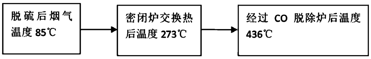
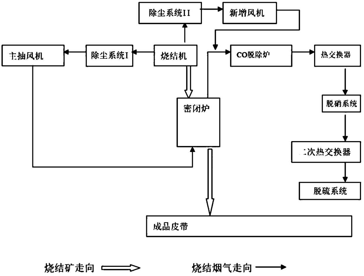
[0031] The present invention relates to a collaborative treatment process for sinter waste heat and sintering flue gas pollutants. The treatment process includes: the sintering flue gas produced by metallurgical sintering is subjected to dust removal treatment to remove particulate matter and desulfurization treatment to remove SO 2 Afterwards, heat exchange treatment is carried out with the sintered ore produced by metallurgical si...


PUM


Abstract

The invention relates to a sinter waste heat and sintering flue gas pollutant cooperative treatment process. The treatment process comprises the steps that sintering flue gas generated by metallurgy sintering is subjected to dedusting treatment to remove particulate matters to be then subjected to heat exchange treatment with sinter generated by metallurgy sintering, and at least part of CO in thesintering flue gas is oxidized and removed during heat exchange treatment; and the sintering flue gas is subjected to CO desorption treatment, and at least part of CO in the sintering flue gas is oxidized and removed during CO desorption treatment. According to the arrangement conditions of a sintering machine and a gas desulfurization system at present, the sintering flue gas can adopt the technology that SO2 is firstly or lastly desorbed. The cooperative treatment process solves the problems about CO desorption and utilization, and cooperative treatment of sinter waste heat and sintering flue gas pollutant is achieved.

Description

technical field [0001] The invention relates to waste utilization in the metallurgical industry, in particular to the fields of waste heat utilization and pollutant treatment. Background technique [0002] In today's context of global warming and deterioration of the ecological environment, the energy saving and emission reduction of sintering is of great significance to the sustainable development of the steel industry. According to statistics, the energy consumption of the sintering process accounts for more than 15% of the energy consumption of the entire iron and steel industry, and the pollutant discharge accounts for about 40% of the entire iron and steel industry. In recent years, with the country's increasing attention to energy conservation and emission reduction, sinter waste heat utilization and sintering machine head flue gas pollutants such as dust and SO have appeared in the sintering field. 2 treatment technology, and with the improvement of national environm...

Claims


Application Information

Patent Timeline
Patent Type & Authority Applications(China)
IPC IPC(8): F27D17/00
CPCF27D17/004F27D17/008
Inventor 杨清海
Owner 杨清海
Why Eureka
Try Eureka