Device used for high-efficiency processing and fugitive emission of VOCs

A fugitive emission and high-efficiency technology, applied in gas treatment, membrane technology, dispersed particle separation, etc., can solve the problems of difficult large-scale and effective treatment of VOCs, low device treatment efficiency, etc., to improve the utilization rate and service life. Liquid separation effect, avoid excessive sinking effect

Pending Publication Date: 2018-11-02
GUANGDONG J TECH ENVIRONMENT SCI CO LTD
View PDF7 Cites 4 Cited by
  • Summary
  • Abstract
  • Description
  • Claims
  • Application Information

AI Technical Summary

Problems solved by technology

This technical solution utilizes the characteristics of high-performance catalysts to independently decompose VOCs, and solves problems such as secondary pollution. However, the treatment efficiency of the device is not high, and it is difficult to effectively treat VOCs emitted by point sources on a large scale.

Method used


Image

  • Device used for high-efficiency processing and fugitive emission of VOCs
  • Device used for high-efficiency processing and fugitive emission of VOCs
  • Device used for high-efficiency processing and fugitive emission of VOCs

Examples


Embodiment 1

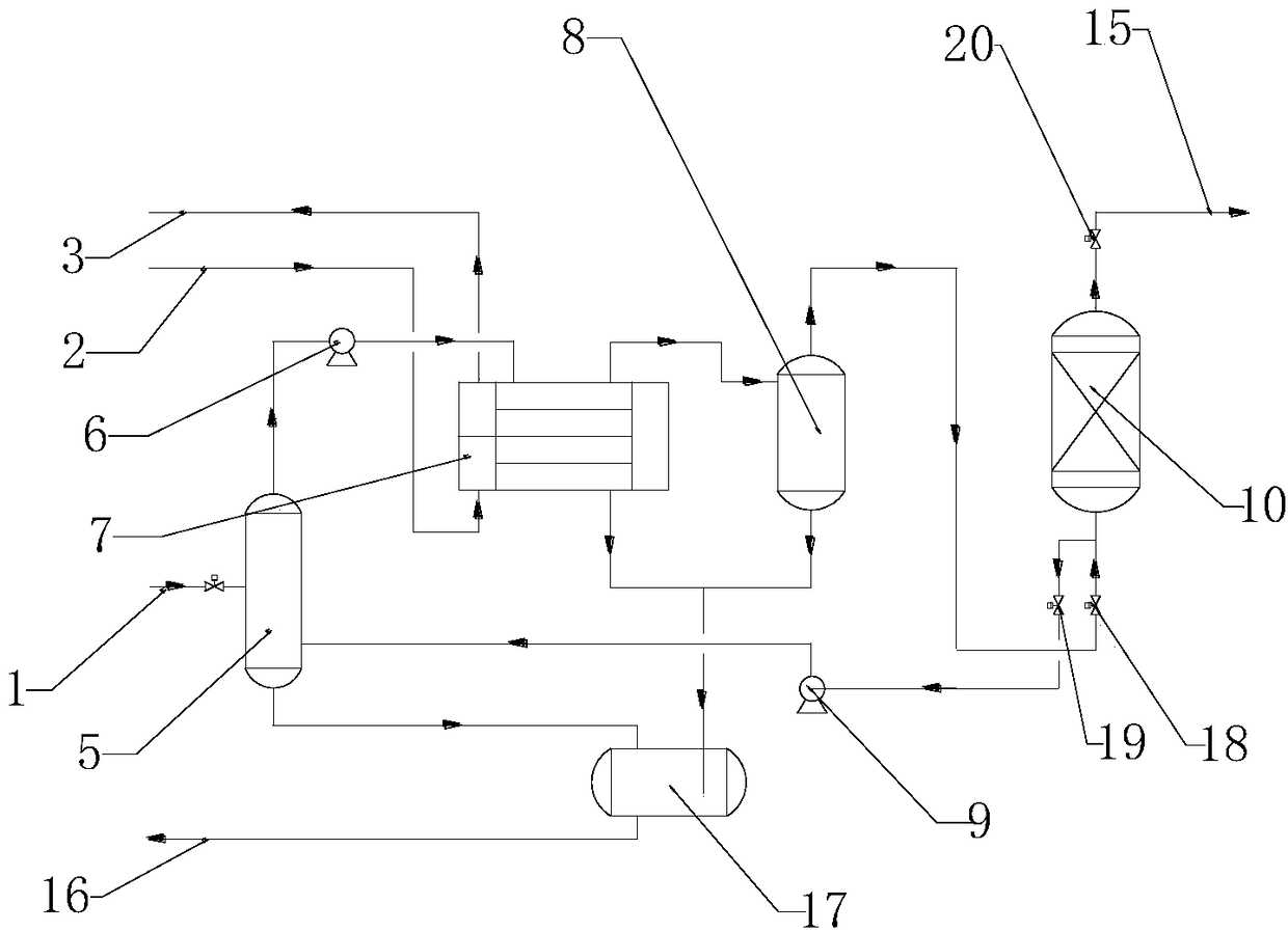
[0038] A device for efficiently treating fugitive emissions of VOCs, such as figure 2 As shown, it includes a buffer tank 5, a blower 6, a condenser 7, a gas-liquid separation tank 8, and an adsorption tower unit 10 connected sequentially through the flue gas pipeline. Enter the buffer tank 5, the gas-liquid separation tank 8 is connected with the adsorption tower unit 10 through the adsorption pipeline, the adsorption valve 18 is arranged on the adsorption pipeline, and the gas outlet valve 20 is arranged on the gas outlet pipeline at the top of the adsorption tower. VOCs waste gas from unorganized emission enters the adsorption tower unit 10 for adsorption treatment and then is discharged through the flue gas outlet 15 by opening the outlet valve 20;

[0039] Vacuum pump 9 and described adsorption tower unit 10 are connected by desorption pipeline, and described desorption pipeline is provided with desorption valve 19, and described vacuum pump 9 is connected with surge tan...

Embodiment 2

[0051] This embodiment only describes the differences from Embodiment 1.

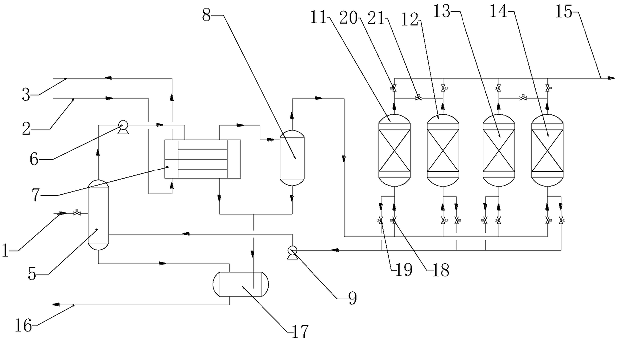
[0052] Such as figure 1 As shown, the adsorption tower unit 10 includes a first adsorption tower 11, a second adsorption tower 12, a third adsorption tower 13, and a fourth adsorption tower 14. The first adsorption tower 11, the second adsorption tower 12, the third adsorption tower The bottoms of the adsorption tower 13 and the fourth adsorption tower 14 are all provided with an adsorption valve 18 and a desorption valve 19, and the tops of the first adsorption tower 11, the second adsorption tower 12, the third adsorption tower 13, and the fourth adsorption tower 14 Both are provided with an outlet valve 20, between the first adsorption tower 11 and the second adsorption tower 12, between the third adsorption tower 13 and the fourth adsorption tower 14, a balance valve 21 is arranged, and the balance valve 21 is used for Balance the pressure between the two towers. As mentioned above, this device a...


PUM

PropertyMeasurementUnit
thicknessaaaaaaaaaa
thicknessaaaaaaaaaa
thicknessaaaaaaaaaa

Abstract

The invention discloses a device used for high-efficiency processing and fugitive emission of VOCs. The device comprises a buffer tank, a blower fan, a condenser, a gas-liquid separation tank, and anadsorption tower unit which are connected successively; the adsorption tower unit and a vacuum pump are connected through a desorption pipeline; the desorption pipeline is provided with a desorption valve; the vacuum pump is connected with the buffer tank; the vacuum pump is used for conveying desorption gas from the desorption tower unit into the buffer tank from bottom to top; a presser sensor is arranged in the buffer tank; the condenser and the gas-liquid separation tank are connected with a liquid storage tank; and the liquid storage tank is provided with a waste liquid outlet. The devicecomprises the advantages of condensing method and adsorption method, a high efficiency stable operation comprehensive treatment technology process is formed, the newest national emission standards are achieved at relatively low investment and operation cost, and no secondary pollution is caused.

Description

technical field [0001] The invention relates to the field of environmental protection technology, and relates to a method for treating VOCs gas by means of physical technology, in particular to a device for efficiently treating fugitive emission of VOCs. Background technique [0002] Organic waste gas, also known as VOCs, mainly includes hydrocarbons, aromatic hydrocarbons, alcohols, aldehydes, ketones, lipids, amines and organic acids, etc. It is generally considered that the melting point is lower than room temperature, and the boiling point range is between 50 and 260 ° C Volatile organic compounds among them have the characteristics of strong volatility, special odor, irritation and toxicity, which will not only adversely affect the ecological environment, but also cause serious harm to human health. VOCs treatment technology can be divided into two categories: one is recovery technology, which enriches and separates VOCs by changing physical conditions such as temperatu...

Claims


Application Information

Patent Timeline
Patent Type & Authority Applications(China)
IPC IPC(8): B01D53/00B01D53/04
CPCB01D53/002B01D53/04B01D2257/708B01D2259/40083B01D2253/25
Inventor 杨颖欣钟璐胡小吐刘勇胡静龄薛学良
Owner GUANGDONG J TECH ENVIRONMENT SCI CO LTD
Why Eureka
Try Eureka