Flexible antenna and patch preparation method thereof

A flexible antenna and patch technology, used in antennas, antenna parts, antennas suitable for movable objects, etc., can solve problems such as limited application and no flexibility, and achieve beautiful patterns, good flexibility, and rich colors. Effect

Active Publication Date: 2018-11-02
ANHUI UNIVERSITY OF TECHNOLOGY AND SCIENCE
View PDF10 Cites 4 Cited by
  • Summary
  • Abstract
  • Description
  • Claims
  • Application Information

AI Technical Summary

Problems solved by technology

However, due to its rigidity and lack of softness, its application

Method used


Image

  • Flexible antenna and patch preparation method thereof
  • Flexible antenna and patch preparation method thereof
  • Flexible antenna and patch preparation method thereof

Examples


preparation example Construction

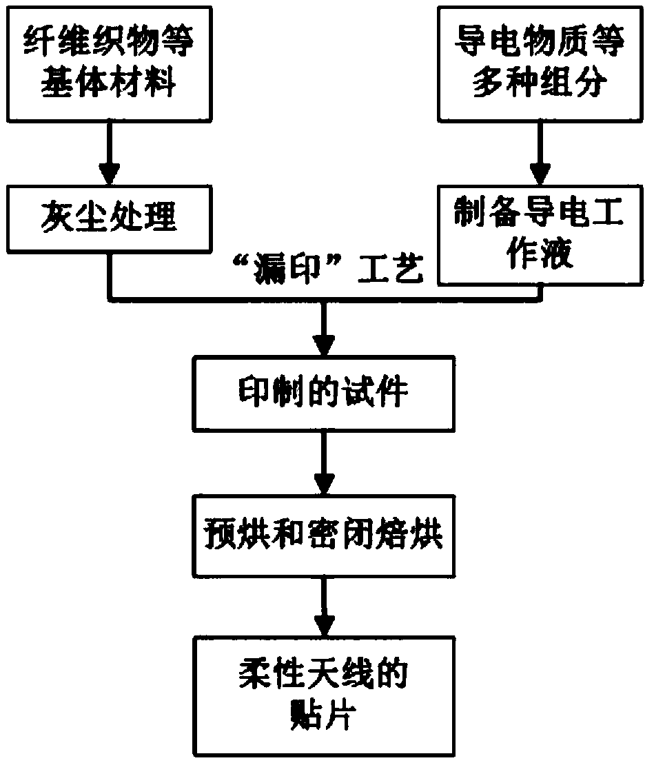
[0028] Such as figure 1 As shown, the specific preparation method of the flexible antenna patch of the present invention includes the following steps:

[0029] 1) First, process the flexible media matrix materials such as fiber fabrics, cut them into suitable sizes, and blow off the dust on the surface in a vacuum environment (0.3-0.5 atmospheres) to eliminate electrostatic effects and reduce the impact of dust on the process and performance The impact

[0030] 2) Fix the flexible medium base material on the printing platen;

[0031] 3) Conductive working fluid is prepared from multiple components according to the following formula;

[0032] 4) Place the conductive working fluid in the color frame of the flat screen or rotary screen printing machine, and the automatic control mechanism controls the automatic lifting, automatic shift and automatic printing of the color frame;

[0033] 5) Using the "missing printing" process, the conductive working fluid is leaked onto the carrier (flex...

Embodiment 1

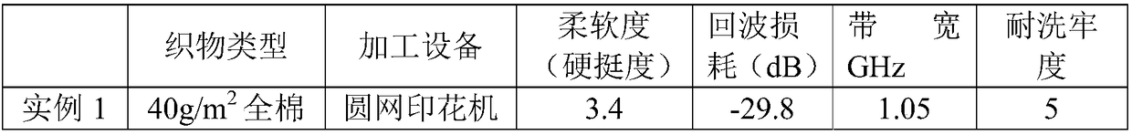
[0050] At 40g / m 2 The cotton plain weave fabric is used as the flexible medium matrix material to prepare the flexible antenna patch. The specific preparation method is as follows:

[0051] 1) Cut the above-mentioned cotton plain weave fabric to a suitable size, and blow off the dust on the surface in a vacuum environment of 0.4 atmospheres to eliminate the electrostatic effect and reduce the influence of dust on the process and performance;

[0052] 2) Fix the processed cotton plain weave fabric on the printing platen;

[0053] 3) Preparation of conductive working fluid:

[0054] ① Conductive component: Weigh 10kg conductive component; among the conductive components, nano silver powder 2 kg, graphene 0.5 kg, nano zinc oxide 0.5 kg, nano copper oxide 1 kg, aluminum oxide 1 kg, nano titanium dioxide 1.5 kg, nano three 1kg of iron oxide, 1kg of tin oxide, 1kg of nano aluminum powder and 0.5kg of zinc chloride;

[0055] ②Binder components: LA132 type water-based adhesive 3kg; water-based...

Embodiment 2

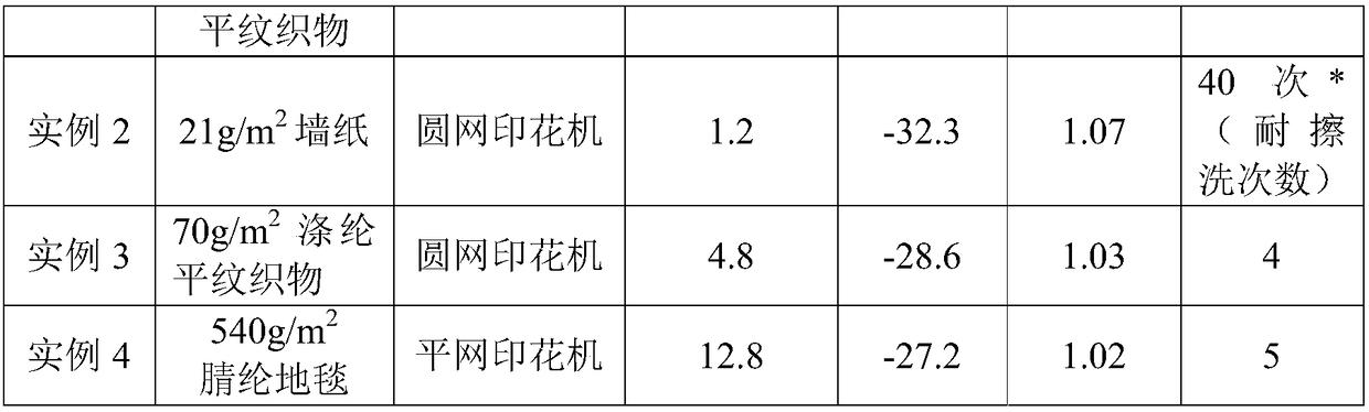
[0065] The difference between this embodiment and embodiment 1 is that this embodiment uses 21g / m 2 Wallpaper is used as a flexible medium base material. In the method steps, infrared pre-baking or oven pre-baking is used for 30 seconds, the pre-baking temperature is about 100°C, the airtight baking is 4 minutes, and the baking temperature is about 118°C to prepare the flexible antenna patch. Then the flexible antenna is processed.


PUM


Abstract

The invention discloses a flexible antenna and a patch preparation method thereof. The preparation method comprises the following steps: (1) removing dust from a flexible dielectric substrate; (2) biting conductive working fluid onto the pretreated flexible dielectric substrate to obtain a printed test piece; and (3) drying the test piece through prebaking and closed baking to form a flexible antenna patch. The flexible antenna disclosed by the invention breaks through the rigid property of a traditional antenna, has the softness of textile fibers, relates to a two-dimensional space, can be widely applied to the field of vehicle decorations, clothing and costumes, can be also fitted with materials such as a wall body and glass, has a product advantage of secondary development, can meet themarket requirements and has a relatively high development and application prospect.

Description

Technical field [0001] The invention belongs to the field of antenna technology, and specifically relates to a flexible antenna and a method for preparing a patch. Background technique [0002] Microstrip antenna is a commonly used low-profile antenna, which is often used in airborne and missile-borne equipment. The substrate material of the traditional microstrip antenna is a rigid flat material with a certain thickness, so the finished microstrip antenna is also flat. However, due to its rigidity and lack of softness, it limits its application in the fields of car decoration, clothing and apparel. Summary of the invention [0003] The present invention aims to solve at least one of the technical problems existing in the prior art. To this end, the present invention provides a flexible antenna and a method for preparing a patch thereof. The purpose is to make the antenna not only have the softness of textile fibers, but also meet the requirements of the actual electromagnetic p...

Claims


Application Information

Patent Timeline
IPC IPC(8): H01Q1/38H01Q1/32H01Q1/27
CPCH01Q1/273H01Q1/32H01Q1/38
Inventor 孙瑞霞王宗乾李俊余纪文杨海伟杨道
Owner ANHUI UNIVERSITY OF TECHNOLOGY AND SCIENCE
Why Eureka
Try Eureka