Multi-flue closed connecting bridge pipe for clean coke oven

A closed and clean technology, applied in the field of riser pipes, can solve the problems that the coke cake cannot be uniformly matured, the flow rate adjustment of high temperature liquid cannot be realized, and the temperature drops.

Inactive Publication Date: 2018-11-06
JIANGSU ZHONGLEI ENERGY SAVING TECH DEV CO LTD
View PDF0 Cites 2 Cited by
  • Summary
  • Abstract
  • Description
  • Claims
  • Application Information

AI Technical Summary

Problems solved by technology

However, with the enlargement of coke ovens, as well as the increase in output and production capacity, the capacity of each carbonization chamber in each row of coke ovens increases, and the section length of the riser channel increases accordingly, forming a narrower rectangle. The increase of the length of the rectangular hole pipe and the rectangular hole pipe makes its structural stability worse. In addition, the high-temperature airflow flowing through the riser pipe on the wall of the narrow and long hole also forms a negative pressure effect on the long wall. Furnace not working properly
Moreover, because the existing coke oven riser is directly connected between the combustion chamber and the gas collecting pipe, the flow velocity of the high-temperature liquid cannot be adjusted, and the flow velocity and temperature of the high-temperature fluid directly affect the fluctuation of the temperature of the carbonization chamber. The air flow rate will reduce the temperature in the carbonization chamber, so that the coke cake in the carbonization chamber cannot be uniformly matured to form green coke, which seriously affects the quality of coke formation

Method used


Image

  • Multi-flue closed connecting bridge pipe for clean coke oven
  • Multi-flue closed connecting bridge pipe for clean coke oven
  • Multi-flue closed connecting bridge pipe for clean coke oven

Examples


Embodiment Construction

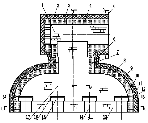
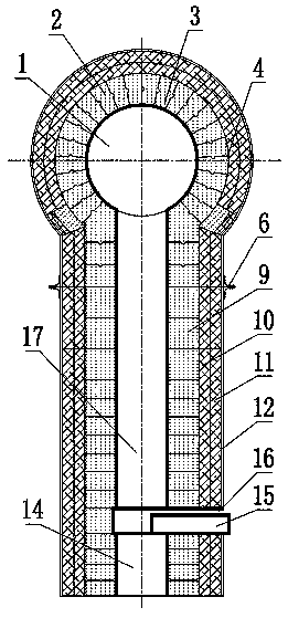
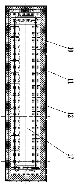
[0021] Such as figure 1 , figure 2 As shown in the clean coke oven multi-flue closed connecting bridge tube, the riser casing 12 of the riser is made of thin steel plates, and the riser includes a riser connection section 7 and a riser diversion section 8, and the riser connection section 7 and the pipe wall of the riser diversion section 8 adopt the same structure, and the pipe walls of the two sections are the riser masonry layer 9, the riser fire-resistant insulation board layer 10, and the riser fire-resistant insulation fiber layer from the inside to the outside. 11 and riser shell 12. The riser masonry layer 9 is made of erosion-resistant mullite bricks, the riser fire-resistant insulation board layer 10 is laid with aluminum silicate fiber board, and the riser pipe fire-resistant insulation fiber layer 11 is filled with aluminum silicate fiber blanket , the fire-resistant and heat-insulating fiber layer can also be a zirconium-containing fiber layer or a calcium sili...


PUM

PropertyMeasurementUnit
compressive strengthaaaaaaaaaa
porosityaaaaaaaaaa

Abstract

The invention discloses a multi-flue closed connecting bridge pipe for a clean coke oven. Corundum, mullite, pyrophyllite, boron nitride, cordierite, trace silicon carbide, Al2O3 micro powder, kaolinand a ZrO2 micro powder composite binder are taken as materials, compressive strength MPa is higher than or equal to 10, thermal conductivity at 350 DEG C is lower than or equal to 0.25, and porosity(%) is larger than or equal to 70. A gas collecting pipe is movably supported at the top end of a bridge pipe connecting section of the connecting bridge pipe, a bridge pipe inner masonry wall is built at the lower part of a pipe cavity of a bridge pipe diversion section, at least two high-temperature flue gas channels are formed in the bridge pipe inner masonry wall, and channel gates are inserted into upper openings of the high-temperature flue gas channels; a pipe top insulation layer and a pipe bottom insulation layer which are mutually connected are arranged circumferentially at the crosssection of the gas collecting pipe; gate insertion ports are formed in the pipe wall of an ascending pipe diversion section. The connecting bridge pipe not only has stable structure, low flue gas conveying resistance and high collapse resistance, but also can control the flow and rate of high-temperature flue gas in an ascending pipe, and coke forming quality is high.

Description

technical field [0001] The invention relates to coking thermal equipment, in particular to a rising pipe of a clean heat recovery coke oven. Background technique [0002] Coking is a process in which raw coal is decoked by pyrolysis and combustion in a coke oven. The kiln used to make coke is called a coke oven; during the coking process, raw coal will emit a large amount of high-temperature flue gas, that is, raw gas. The clean heat recovery coke oven is a new type of coke oven that burns the waste gas and some harmful substances produced in the coking process reasonably and fully inside the coke oven, and recovers the heat of the high-temperature exhaust gas for power generation or other purposes. [0003] The clean heat recovery coke oven rising pipe is a key component connecting the combustion chamber and the gas collecting pipe, and the high-temperature waste heat enters the gas collecting pipe through the coke oven rising pipe. The riser is the highest temperature par...

Claims


Application Information

Patent Timeline
Patent Type & Authority Applications(China)
IPC IPC(8): C10B27/00
CPCC10B27/00
Inventor 李凤朱云芳
Owner JIANGSU ZHONGLEI ENERGY SAVING TECH DEV CO LTD
Why Eureka
Try Eureka