Sulfur resource recovery method and device making incineration, resolution, charcoal head reduction coordinated

A technology of resource recovery and sulfur recovery, which is applied in the field of air pollutant control and resource utilization, can solve the problems of difficult storage and transportation of sulfuric acid, and small application range, and achieve broad market application prospects, high-efficiency regeneration, and sulfur resource recovery. Effect

Inactive Publication Date: 2018-11-13
SHANDONG UNIV
View PDF5 Cites 7 Cited by
  • Summary
  • Abstract
  • Description
  • Claims
  • Application Information

AI Technical Summary

Problems solved by technology

But liquid SO 2 The application range is small, and sulfuric acid is difficult to store and transport
However, there is no mature and widely applicable SO 2 Technology of reducing and recovering sulfur

Method used


Image

  • Sulfur resource recovery method and device making incineration, resolution, charcoal head reduction coordinated
  • Sulfur resource recovery method and device making incineration, resolution, charcoal head reduction coordinated

Examples


Embodiment 1

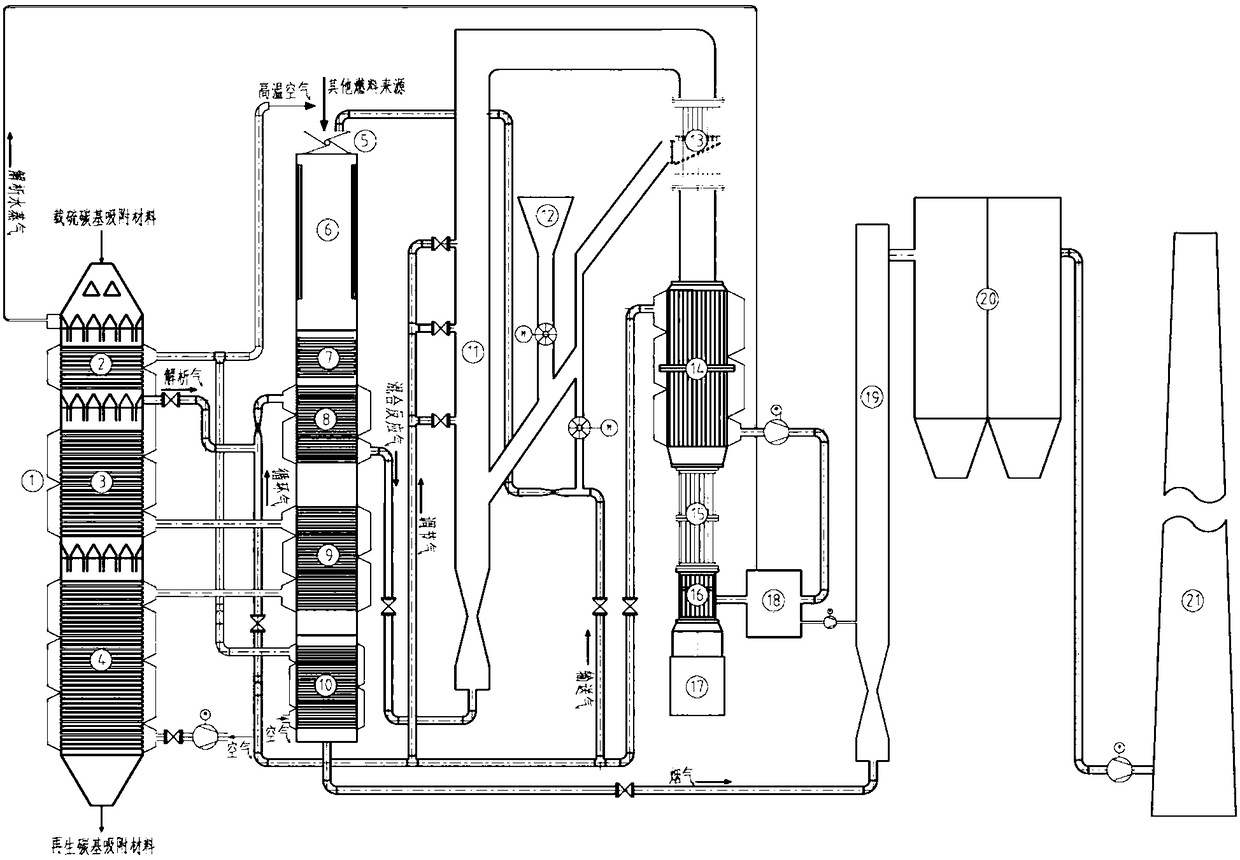
[0079] Such as figure 1 As shown, the desorption tower 1 includes a vertical tower body, and the tower is divided into a preheating section 2, a desorption section 3 and a cooling section 4, and heat exchange pipes are arranged horizontally in each section. The sulfur-loaded carbon-based adsorbent enters the tower from the upper part of the desorption tower 1, and successively passes through the space between the preheating section 2, desorption section 3, cooling section 4 and their respective internal heat exchange pipes. The incinerator 6 includes a vertical furnace body with a burner 5 on the top of the furnace. The incineration flue gas passes through the space between the rear heating surface shell and the heat exchange pipe, the acid gas removal tower 19, the dust collector 20 and the chimney 21 in sequence. , the conveying power is provided by the induced draft fan, and the rear heating surface includes an economizer 7, a mixed reaction gas heater 8, a secondary air he...

Embodiment 2

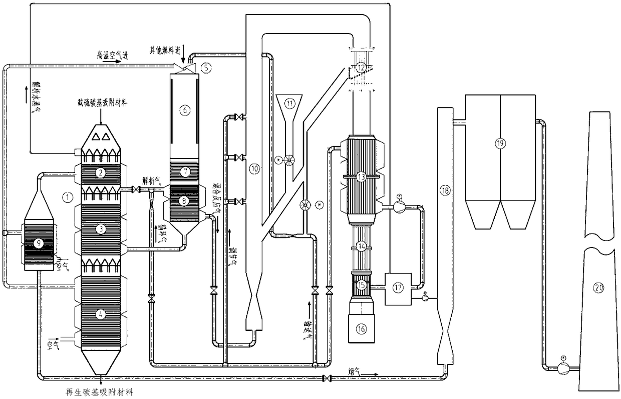
[0092] Such as figure 2As shown: the desorption tower 1 includes a vertical tower body, and the tower is divided into a preheating section 2, a desorption section 3 and a cooling section 4, and heat exchange pipes are arranged horizontally in each section. The sulfur-loaded carbon-based adsorbent enters the tower from the upper part of the desorption tower 1, and successively passes through the space between the preheating section 2, desorption section 3, cooling section 4 and their respective internal heat exchange pipes. The incinerator 6 includes a vertical furnace body, and a burner 5 is installed on the top of the furnace. The incineration flue gas passes through the space between the rear heating surface shell and the heat exchange pipe, the internal space of the analysis section 3 heat exchange tubes, and the preheating section. 2 The inner space of the heat exchange tubes, the space between the shell of the air heater 9 and the heat exchange pipes, the acid gas remova...


PUM

PropertyMeasurementUnit
particle diameteraaaaaaaaaa
specific surface areaaaaaaaaaaa

Abstract

The invention discloses a sulfur resource recovery method and device making incineration, resolution, charcoal head reduction coordinated. The sulfur resource recovery device comprises a resolution tower, an incineration furnace and a fluidized bed carbon thermal reduction tower, wherein the resolution tower is divided into a preheating section, a resolution section and a cooling section from topto bottom, the bottom of the incineration furnace is connected with a tail heated device, and the tail heated device is sequentially provided with a primary air heater, a secondary air heater, a mixedreaction gas heater from bottom to top. A tube nest outlet of the cooling section is connected with a gas inlet of the secondary air heater, a gas outlet of the secondary air heater is connected witha tube nest inlet of the resolution section, the tube nest outlet of the resolution section is connected with the tube nest inlet of the preheating section, the tube nest outlet of the preheating section and the gas outlet of the primary air heater are both connected with an air inlet of a combustor of the incineration furnace, a resulted gas outlet of the resolution tower is connected with a gasinlet of the mixed reaction gas heater, and a gas outlet of the mixed reaction gas heater is connected with a resulted gas inlet of the fluidized bed carbon thermal reduction tower.

Description

technical field [0001] The invention belongs to the field of air pollutant control and resource utilization, and in particular relates to incineration heating, active coke analysis and charcoal thermal reduction of SO 2 Sulfur resource recovery device and process coordinated by the three processes of preparing sulfur. Background technique [0002] In view of the current development trend of environmental protection technology, resource-based and sustainable coal-fired flue gas SO 2 The removal process is becoming the development direction of the current environmental protection technology. Currently the most widely used SO 2 The removal technology is limestone wet desulfurization technology. This technology consumes a large amount of limestone resources and water resources. The utilization rate of the by-product desulfurization gypsum is low, and the desulfurization wastewater is difficult to treat. It brings a large amount of wastewater and waste solid discharge, causing ...

Claims


Application Information

Patent Timeline
Patent Type & Authority Applications(China)
IPC IPC(8): B01D53/04C01B17/04
CPCB01D53/0438B01D2257/302C01B17/0482Y02P20/129
Inventor 马春元赵希强冯太夏霄李军张世珍
Owner SHANDONG UNIV
Why Eureka
Try Eureka