Control valve and centrifugal micro-fluidic chip

A microfluidic chip and control valve technology, applied in fluid controllers, laboratory utensils, laboratory containers, etc., can solve problems such as the influence of the reagent system, exceeding the processing limit, and difficulty in precise control, without complex processing. , easy to use, simple processing effect

Pending Publication Date: 2018-11-13
DONGGUAN HEC MEDICAL INTELLIGENT DEVICE R&D CO LTD
View PDF0 Cites 6 Cited by
  • Summary
  • Abstract
  • Description
  • Claims
  • Application Information

AI Technical Summary

Problems solved by technology

For complex biochemical reactions involving multiple fluids or multiple reaction steps, it is difficult for the above-mentioned control valves to integrate multiple control valves on the same chip, such as capillary valves. Requires a substantial reduction in capillary size, which has exceeded conventional processing limits
It is difficult to precisely control the process of traps, so it is necessary to leave a large margin in the speed control. For example, a difference of 1500rpm must be ensured between two

Method used


Image

  • Control valve and centrifugal micro-fluidic chip
  • Control valve and centrifugal micro-fluidic chip
  • Control valve and centrifugal micro-fluidic chip

Examples


Embodiment 1

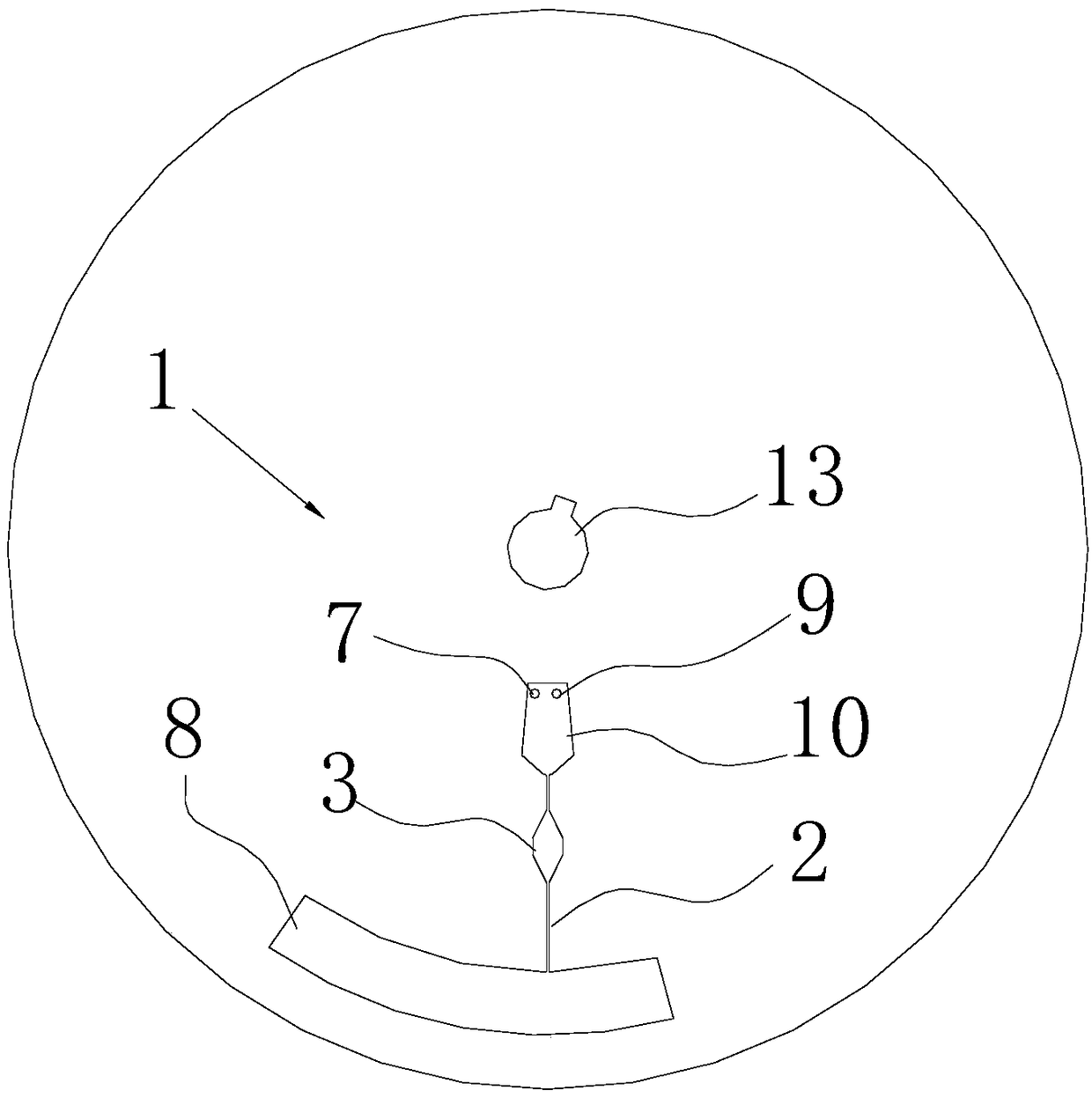
[0049] Such as figure 1 As shown, the present invention provides a control valve, which is arranged on the microfluidic channel 2 of the microfluidic chip. The microfluidic chip includes a chip body 1. As an improvement of the present invention, the control valve includes a valve cavity 3, a reversible water absorption mechanism 4. The reversible water absorption mechanism 4 is set in the valve cavity 3 .

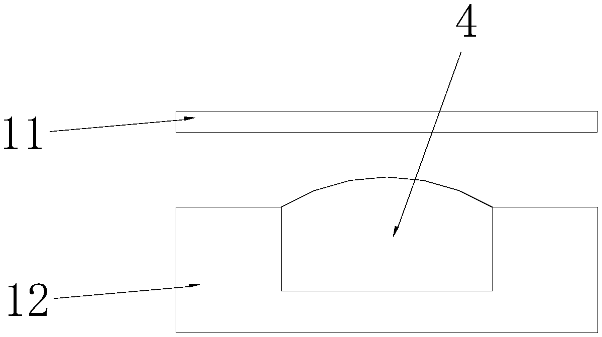
[0050] As a further improvement of the present invention, the reversible water absorption mechanism 4 is packaged in an anti-deformation packaging film (not shown in the figure). The reversible water-absorbing mechanism 4 is one or more of sponge, foam, and water-absorbing fibers. The anti-deformation packaging film is gauze. As shown in FIG. 2 , the chip body 1 includes a chip upper plate 11 and a chip lower plate 12 , and the microfluidic channel 2 and the valve cavity 3 are arranged between the chip upper plate 11 and the chip lower plate 12 .

[0051] The present inv...

Embodiment 2

[0060] The difference between this embodiment and Embodiment 1 is:

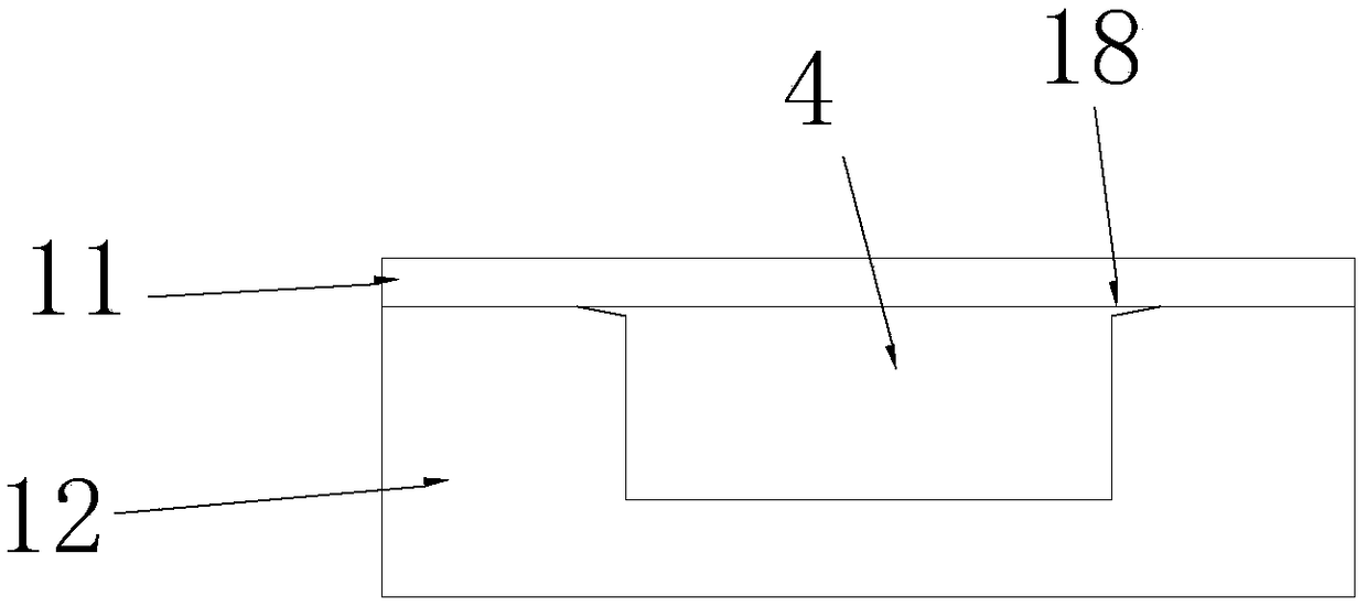
[0061] Such as image 3 As shown, the chip upper board 11 and the chip lower board 12 are provided with a sealing mechanism, and the sealing mechanism is located outside the edge of the valve cavity 3 .

[0062] The sealing mechanism includes matching sealing bosses 5 and sealing grooves 6 ; the sealing bosses 5 are arranged on the chip upper board 11 , and the sealing grooves 6 are arranged on the chip lower board 12 . It is worth noting that the sealing boss 5 can also be arranged on the chip lower board 12 , and the sealing groove 6 is arranged on the chip upper board 11 .

[0063] The cross-sectional shape of the sealing boss 5 is trapezoidal, and the cross-sectional shape of the sealing groove 6 is trapezoidal or rectangular.

[0064] When no sealing mechanism is provided between the upper chip board 11 and the lower chip board 12, as Figure 2a and 2b As shown, when the reversible water-absorbing me...

Embodiment 3

[0067] This embodiment takes the cleaning of magnetic beads in the chemiluminescence reaction process as an example. The chemiluminescence kit generally requires cleaning of the magnetic beads 2-3 times. Through the device of the present invention, after adding the cleaning solution once, the cleaning solution can be quantitatively released successively to realize The process of magnetic bead washing.

[0068] Considering the reagent ratio of chemiluminescence and the characteristics of the centrifugal microfluidic chip, in this embodiment, a total of 60 μL of cleaning solution was released three times.

[0069] Such as Figure 5 As shown, the structure of the centrifugal microfluidic chip used in this embodiment is the same as that of the centrifugal microfluidic chip in the first or second embodiment, and the reaction chamber is the cleaning pool 80 .

[0070] The reversible water absorption mechanism selects the highly water-absorbing and hygroscopic fiber "Hygra" porous m...


PUM

PropertyMeasurementUnit
Sizeaaaaaaaaaa

Abstract

The invention belongs to the technical field of micro-fluidic chips, and discloses a control valve arranged on a micro-fluidic channel (2) of a micro-fluidic chip. The micro-fluidic chip comprises a chip body (1), the control valve comprises a valve cavity (3) and a reversible water absorption mechanism (4), and the reversible water absorption mechanism (4) is arranged inside the valve cavity (3).The invention further discloses a centrifugal micro-fluidic chip comprising a valve body (1), a liquid inlet (7), a reaction cavity (8) and the micro-fluidic channel (2), wherein the centrifugal micro-fluidic chip further comprises a control valve arranged between the liquid inlet (7) and the reaction cavity (8), and the control valve is the control valve disclosed in the invention. According tothe control valve and the centrifugal micro-fluidic chip provided by the invention, the process is simple, complex processing is not needed, step-by-step release of a solution can be realized by changing the centrifugal rotational speed, and the control valve is convenient to use.

Description

technical field [0001] The invention relates to the technical field of microfluidic chips, in particular to a control valve and a centrifugal microfluidic chip. Background technique [0002] Microfluidics integrates the basic operation units such as sample preparation, reaction, separation, and detection in the biological, chemical, and medical analysis processes into a micron-scale chip to automatically complete the entire analysis process. Due to its great potential in the fields of biology, chemistry, and medicine, it has developed into a new research field interdisciplinary in biology, chemistry, medicine, fluid, electronics, materials, and machinery. Due to the advantages of less sample consumption, fast reaction time, high detection throughput and good integration performance, microfluidic chips are increasingly used in portable detection and other fields. [0003] Centrifugal microfluidic chips, which use centrifugal force as power to realize fluid flow and unit oper...

Claims


Application Information

Patent Timeline
IPC IPC(8): B01L3/00
CPCB01L3/502738B01L2400/06
Inventor 张意如陈跃东庾琼陈立勇刘仁源
Owner DONGGUAN HEC MEDICAL INTELLIGENT DEVICE R&D CO LTD
Why Eureka
Try Eureka