Control method of power transmission system of novel gas-electric hybrid washing and sweeping vehicle

A power transmission system and control method technology, applied in the field of sanitation machinery, can solve problems such as difficult implementation, low load rate of the main engine, and poor emission performance, so as to improve power and fuel economy, reduce fuel consumption and emissions, and reduce installed capacity. The effect of capacity

Active Publication Date: 2018-11-13
HENAN UNIV OF SCI & TECH
View PDF6 Cites 9 Cited by
  • Summary
  • Abstract
  • Description
  • Claims
  • Application Information

AI Technical Summary

Problems solved by technology

In this way, in the cleaning mode, the vehicle mostly travels at a speed of 3-20km/h, the load rate of the main engine is extremely low, the fuel consumption is high, and the emission is poor, and the auxiliary engine runs at high speed, which generates a lot of noise
[0004] Pure electric sweepers have a short driving range, short continuous operation time, and imperfect charging facilities; once the main motor fails, they cannot work. Therefo

Method used


Image

  • Control method of power transmission system of novel gas-electric hybrid washing and sweeping vehicle
  • Control method of power transmission system of novel gas-electric hybrid washing and sweeping vehicle
  • Control method of power transmission system of novel gas-electric hybrid washing and sweeping vehicle

Examples


Embodiment 1

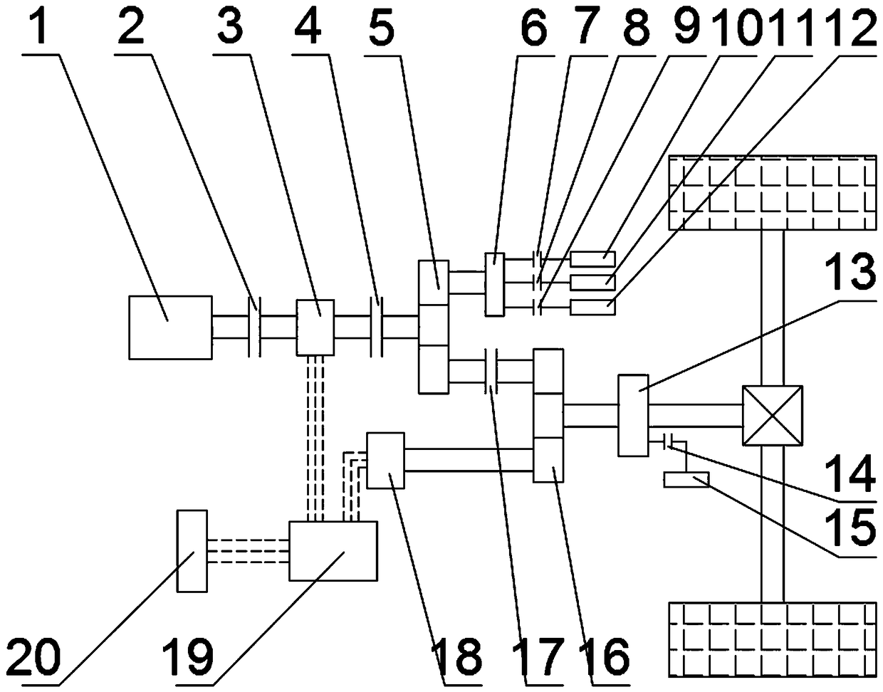
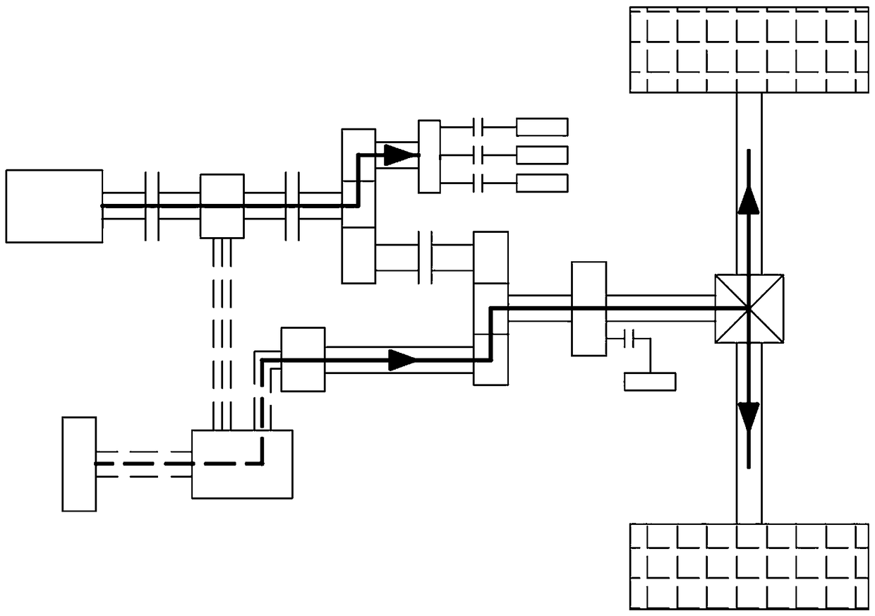
[0088] figure 2 It is the transmission route diagram of the present invention under the operation mode of hybrid electric cleaning with sufficient electric power: the traveling device route is as follows: main motor 18→torque coupling 16→transmission 13→transmission shaft→differential device→wheels; cleaning operation route Engine 1→clutch I2→ISG motor 3→clutch II4→power splitter 5→power take-off 6→working device. In this mode, the low-pressure water pump clutch 14 is closed, the high-pressure water pump clutch 8, the fan clutch 9 and the hydraulic pump clutch 7 are connected, so that the high-pressure water pump 11, the fan 12 and the hydraulic pump 10 are in the working state, the clutch I2 and the clutch II4 are combined, and the clutch III17 Disconnected, the power splitting device and the torque coupling device do not produce a mechanical connection, that is, the main motor 18 is used to drive the vehicle, providing a driving speed of about 7-12km / h, and the satisfied en...

Embodiment 2

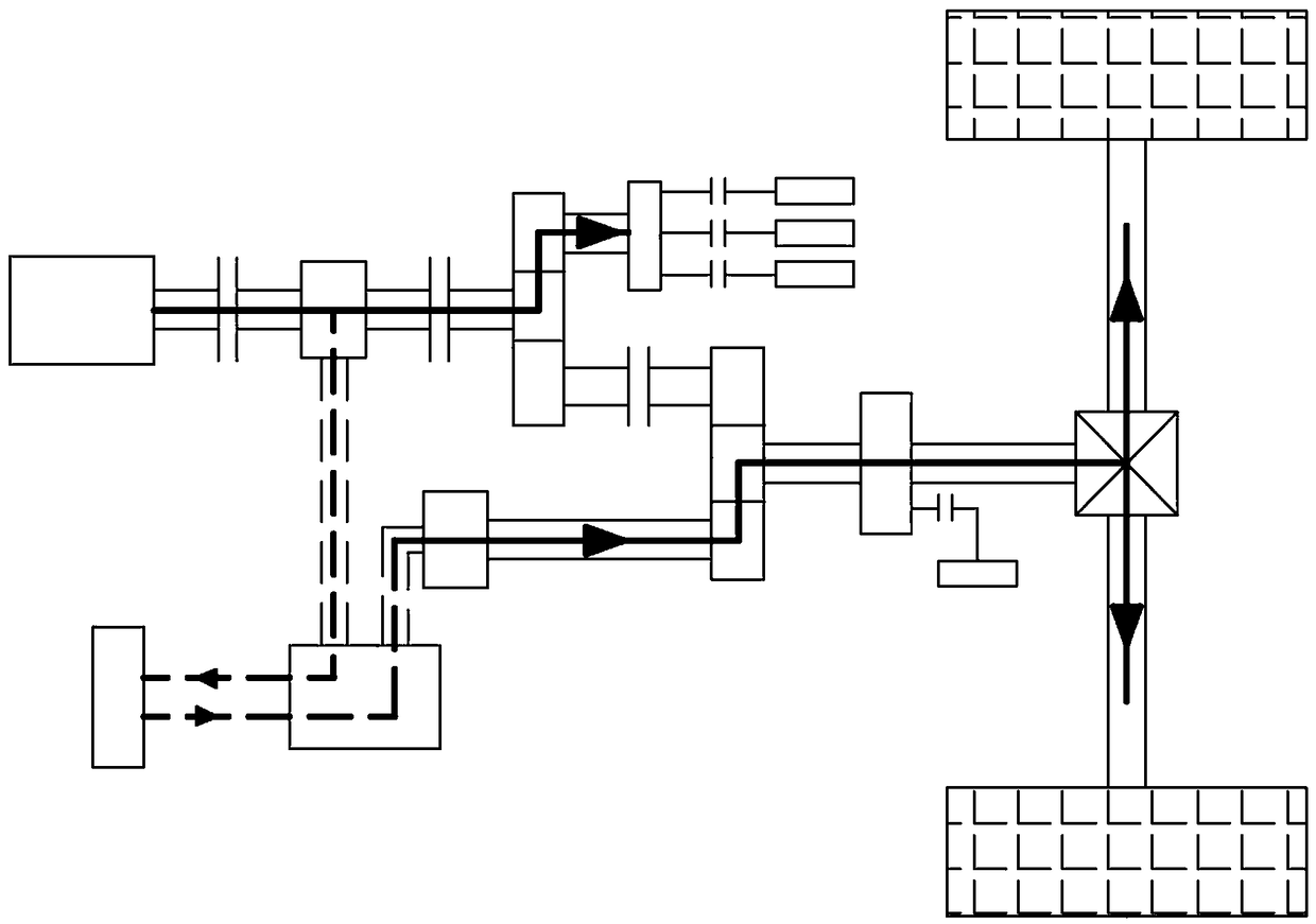
[0090] image 3 It is the transmission route diagram of the present invention under the operation mode of hybrid cleaning with insufficient electricity: the traveling device route is engine 1→clutch I2→ISG motor 3→DC / DC converter 19→battery pack 20→main motor 18→torque Coupler 16→transmission 13→transmission shaft→differential→wheel; the cleaning operation route is engine 1→clutch I2→ISG motor 3→clutch II4→power splitter 5→power take-off 6→working device. By controlling the low-pressure water pump clutch 14 to close, the low-pressure water pump 15 does not work; the high-pressure water pump clutch 8, the fan clutch 9 and the hydraulic pump clutch 7 are connected, and the high-pressure water pump 11, the fan 12 and the hydraulic pump 10 are in the working state; clutch I2, clutch II4 Combining, the clutch III17 is disconnected, part of the power output by the engine 1 charges the battery pack 20 through the ISG motor 3, and part of it provides power to the working device; the s...

Embodiment 3

[0092] Figure 4 It is the transmission route diagram under the no-load transport transfer operation mode of the present invention: at this time, the main motor 18 drives the vehicle alone, and the power transmission route is battery pack 20→DC / DC converter 19→main motor 18→torque coupling 16→ Transmission 13 → transmission shaft → differential → wheels. This process is the process of the cleaning vehicle returning to the garage from the garbage disposal area. There is no sewage in the compartment, and the cleaning vehicle is in the unloaded state in the transition mode. Similar to ordinary light trucks, its route is relatively short. Clutch Ⅰ 2, clutch Ⅱ4. The clutch Ⅲ17 is disconnected, and the vehicle is driven by the main motor 18 alone, and the real-time torque and speed of the main motor 18 are adjusted according to the required torque to meet the requirements of P mot_drive =P req_drive , this mode is the main motor drive mode.


PUM


Abstract

The invention provides a control method for a power transmission system of a novel gas-electric hybrid washing and sweeping vehicle. The control method comprises a transition control method and a sweeping control method. The transition control method is used for switching between different transition working modes, and the different transition working modes include a pure electric mode driven by amain motor during no-load, a coordinated drive mode of the main motor and an ISG motor under on-load transportation, a separate drive mode of an engine under on-load transportation and a combined drive mode of the engine and the main motor under on-load transportation. The sweeping control method is used for switching between two different sweeping working modes, and the sweeping working modes include a pure electric drive mode and an extended-range drive mode. The power transmission system includes a power device, a transmission device and a working device and a traveling device, and the power device transmits power to the working device and the traveling device through the transmission device. The control method for the power transmission system of the novel gas-electric hybrid washingand sweeping vehicle has the advantages of simple and compact structure and convenient arrangement, and realizes the matching between the changed vehicle speed and the sanitation sweeping operation speed when the vehicle runs.

Description

technical field [0001] The invention relates to the field of sanitation machinery, in particular to a control method for a power transmission system of a novel hybrid electric washing and sweeping vehicle. Background technique [0002] The sweeping vehicle is a vehicle that can be used as a road sweeper alone for road cleaning and suction operations; it can also be used as a high-pressure washing vehicle for road cleaning and suction operations; it can also be combined with road cleaning suction and high-pressure flushing. The sweeper is used to realize various combinations of cleaning, washing, and pumping. The vehicle can be widely used in washing and cleaning operations of main roads and viaducts in urban areas. It is a high-efficiency cleaning equipment integrating cleaning, cleaning, decontamination, humidification and cleaning. With the rapid development of highways and urban roads in my country and the great improvement of people's living standards, the hygiene requi...

Claims


Application Information

Patent Timeline
IPC IPC(8): B60K6/44B60L11/12B60W20/16B60W20/15B60W10/06B60W10/08B60W10/02B60W10/30B60L50/15
CPCB60K6/44B60W10/02B60W10/06B60W10/08B60W10/30B60W2300/17B60W2510/244B60W2530/00B60W2710/021B60W2710/0666B60W2710/083B60W2710/30B60W20/15B60W20/16Y02T10/62Y02T10/70Y02T10/7072
Inventor 高爱云付主木张风丽张志超陶发展李勋
Owner HENAN UNIV OF SCI & TECH
Why Eureka
Try Eureka