Robot polishing and grinding force control end effector

A technology of end effector and robot, which is applied in the direction of grinding head, grinding drive device, grinding machine tool parts, etc., can solve problems such as difficult to realize industrial production, poor algorithm stability, slow response speed, etc., and achieve simplified design and guaranteed The effect of grinding quality and small eccentric torque

Active Publication Date: 2018-11-16
GUANGDONG UNIV OF TECH
View PDF5 Cites 8 Cited by
  • Summary
  • Abstract
  • Description
  • Claims
  • Application Information

AI Technical Summary

Problems solved by technology

Because this method needs to realize the control of force and position at the same time, there is force / position coupling, so the realization is more complicated; second, the active force control based on the end tool
Generally speaking, using algorithms to realize impedance control and force / position hybrid control by the controller of the robot has a slow response speed and poor algorithm stability, making it difficult to realize industrial production.

Method used


Image

  • Robot polishing and grinding force control end effector

Examples


Embodiment 1

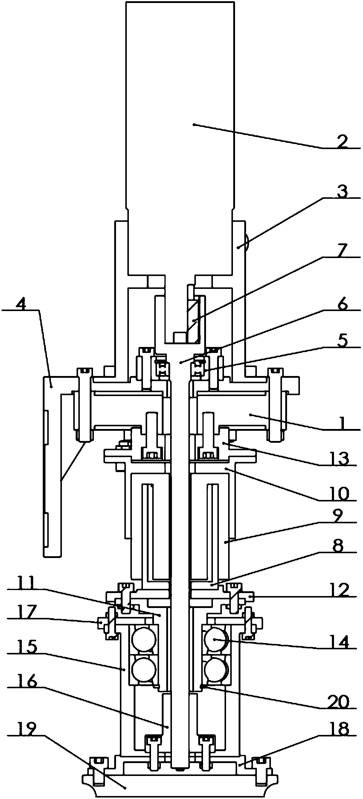
[0030] Such as figure 1 As shown, this embodiment discloses a robot polishing force control end effector, the end effector mainly includes a grinding head for grinding workpieces, a rotating part that drives the grinding head to rotate, and drives the grinding head to perform Give the linear motion department. The rotating part is connected with the mechanical arm, and its output end passes through the linear moving part and is connected with the grinding head in transmission.

[0031] Specifically, the rotating part includes an air motor 2 , a motor bracket 3 , an L-shaped connector 4 , a main shaft 6 , a key 7 , and a bearing assembly 5 . One side of the L-shaped connecting piece 4 is fixedly connected with the grinding mechanical arm, and the air motor 2 is fixedly installed on the other side of the L-shaped connecting piece 4 through the motor bracket 3 . One end of the main shaft 6 is connected to the output end of the air motor 2 through the key 7, and the other end is...

Embodiment 2

[0041] According to the polishing process, a novel robot end polishing actuator is invented. In the present invention, the cutting speed is provided by the air motor 2 of the polishing actuator, avoiding the use of a motor, and greatly reducing the mass of the responding part of the actuator. The polishing actuator can realize the force control of the polishing tool, avoid adjusting the parameters in the polishing operation through the robot controller, and improve the responsiveness of the polishing system. At the same time, the force is also used as a signal to realize the position control of the robot and the feed speed control during the polishing operation. The polishing force and rotary cutting speed can be changed according to the workpieces of different materials and the cutting volume of workpieces.

[0042] The fixed part of the front end of the air motor 2 is clamped by the motor bracket 3 with screws, and the motor bracket 3 and the L-shaped connector 4 are connec...

Embodiment 3

[0049] The polishing force control end effector can be installed on the end joint of the robot through the L-shaped connecting plate 4, and the actuator and the robot together constitute a macro-micro robot polishing system. The robot provides the feed movement during the polishing process, and the actuator provides the polishing speed and polishing tool force.

[0050] Turn on the switch of the air pump to provide the air source to the air motor 2, and the shaft of the air motor 2 rotates. The main shaft 6 and the air motor 2 are connected through the key 7. The speed and torque of the air motor 2 are transmitted to the main shaft 6. The main shaft 6 is used in conjunction with the ball spline 16. The grinding head provides the cutting speed of polishing by the rotation of abrasive material 19.

[0051] The lower surface of the L-shaped connecting plate 4 is equipped with a tension-torsion composite sensor 1 through bolts, which can detect the polishing force during the poli...


PUM


Abstract

The invention discloses a robot polishing and grinding force control end effector. The robot polishing and grinding force control end effector comprises a rotation part, a linear motion part and a grinding head part. A pneumatic motor is adopted as a power source for the effector, and the total mass of the effector is effectively reduced. Usage of a coupler is avoided, accordingly, the complexityof the mechanism is reduced, and the structure is more compact. The rotation movement of the pneumatic motor is transmitted to a ball spline through a main shaft, and the ball spline transmits the rotation movement to the grinding head part. Since the ball spline has the functions of torque transmission and untight connection, mechanical decoupling of the two freedom degrees of a grinding head isachieved at the position of the ball spline. Compared with the current situation that connection of an effector and a macro robot system is conducted at the top end of the effector, by means of the robot polishing and grinding force control end effector, the polished and ground surface capsizing moment is effectively reduced, and the polishing and grinding quality is improved. By means of the robot polishing and grinding force control end effector, control over the polishing and grinding tool force, the polishing and grinding rotation speed and other important polishing and grinding parameterscan be achieved, the effector is simple in structure, small in mass and high in force control precision and response speed.

Description

technical field [0001] The invention relates to the technical field of automation equipment and robots, in particular to a robot polishing force-controlled end effector. Background technique [0002] With the rapid development of industrial robots, their applications in various industrial fields are becoming more and more extensive. In some contact operations, industrial robots are required to have the ability to perceive and control contact force to meet the requirements of precision operations, such as grinding, polishing and assembly operations. During the grinding and polishing operation, the processing tool wears with use, resulting in surface position error, which changes the contact force and affects the processing effect. Therefore, realizing the constant force contact between the tool and the workpiece has important practical significance for the application of industrial robots in contact operations. [0003] Grinding, as a typical example of contact work, requir...

Claims


Application Information

Patent Timeline
Patent Type & Authority Applications(China)
IPC IPC(8): B24B41/00B24B41/04B24B47/00
CPCB24B41/002B24B41/04B24B47/00Y02P70/10
Inventor 管贻生刘喜能李坚张涛
Owner GUANGDONG UNIV OF TECH
Why Eureka
Try Eureka