Micro-flow control system, normally-closed micro-valve and control method

A technology of microfluidic control system and microvalve, which is applied in valve devices, engine components, mechanical equipment, etc., can solve the problems of inability to achieve precise control, increase the difficulty of chip manufacturing, and inability to achieve micron level, etc. The effect of advanced production and commercial use, low requirements for processing equipment and raw materials, and a single wavelength

Pending Publication Date: 2018-11-20
HUNAN LEGEND AI CHIP BIOTECH CO LTD
View PDF1 Cites 0 Cited by
  • Summary
  • Abstract
  • Description
  • Claims
  • Application Information

AI Technical Summary

Problems solved by technology

However, this patent uses ice as the spool, so it cannot be used for storage of reagents, and there is no spool under normal conditions; further, ice is easy to react with reagents, and ice is too large as a spool (it cannot be used as a valve core). to the micron level), precise control cannot be achieved. In addition, if the patent is used on a microfluidic chip, then the chip needs to be implanted with circuits, which will further increase the difficulty of chip manufacturing and reduce its reliability.

Method used


Image

  • Micro-flow control system, normally-closed micro-valve and control method
  • Micro-flow control system, normally-closed micro-valve and control method
  • Micro-flow control system, normally-closed micro-valve and control method

Examples


Embodiment Construction

[0041] The present invention will be described in detail below with reference to the accompanying drawings and examples. It should be noted that, in the case of no conflict, the embodiments of the present invention and the features in the embodiments can be combined with each other. For the convenience of description, if the words "up", "down", "left" and "right" appear in the following, it only means that the directions of up, down, left and right are consistent with the drawings themselves, and do not limit the structure.

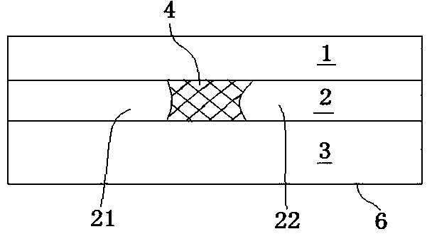
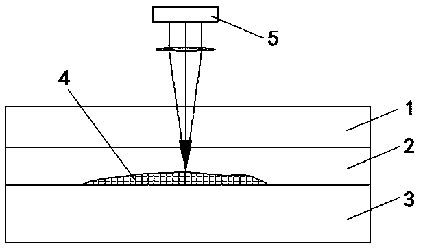
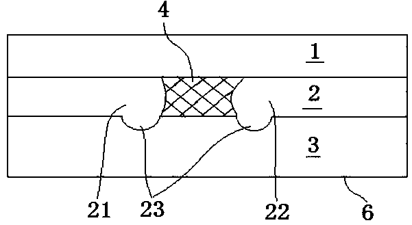
[0042] A microfluidic system, such as figure 2 As shown, it includes a laser light source 5 arranged on the outside of the chip and as figure 1 As shown in the normally closed microvalve, the laser light source 5 is used to melt or vaporize the valve core 4 of the normally closed microvalve to open the normally closed microvalve. Such as figure 1 As shown, the microfluidic pipeline 2 is provided with a valve core 4, which divides the microfluidic pipe...


PUM

PropertyMeasurementUnit
Melting pointaaaaaaaaaa
Diameteraaaaaaaaaa
The inside diameter ofaaaaaaaaaa

Abstract

The invention discloses a micro-flow control system, a normally-closed micro-valve and a control method. The normally-closed micro-valve comprises a micro-flow pipeline which is formed inside a base body; a valve element is arranged inside the micro-flow pipeline and is used for dividing the micro-flow pipeline into a first pipeline and a second pipeline; when the valve element is molten or gasified, the first pipeline communicates with the second pipeline; the valve element and the wall of the micro-flow pipeline are made from the same material; and a transparent material is arranged betweenthe outer wall surface of the base body and the valve element. The micro-valve disclosed by the invention is simple in structure, can solve the problem of integration of the micro-valve and the micro-flow control system and greatly reduces the machining difficulty because the valve element and the wall of the micro-flow pipeline are made from the same material, so the production cost is lowered.

Description

technical field [0001] The invention relates to a microfluidic control system, a normally closed microvalve and a control method, belonging to the field of micron-level valve control. Background technique [0002] The microvalve microfluidic system in the microfluidic system refers to the use of microfabrication technology to integrate various operational analysis functions involved in the field of biology or chemistry, such as sample pretreatment, mixing, reaction, separation and detection, etc. into a microchip. on the analysis system. Microfluidic chips have the advantages of miniaturization, integration, high efficiency, rapidity, minimal reagent consumption and low cost, and can be widely used in many fields such as biomedicine, disease diagnosis and treatment, environmental detection and protection, military and space exploration, etc. , is the frontier and hot spot of current technological development. As the key executive component of the microfluidic system, the m...

Claims


Application Information

Patent Timeline
IPC IPC(8): F16K99/00
CPCF16K99/0036
Inventor 邬鹏程周孝祥向苏民
Owner HUNAN LEGEND AI CHIP BIOTECH CO LTD
Why Eureka
Try Eureka