Optical fiber temperature sensing probe and demodulation method

A technology for sensing the temperature of probes and optical fibers, applied in thermometers, thermometers with physical/chemical changes, instruments, etc., can solve the problems of expensive preparation, complex preparation, and high production costs, and achieve the effect of improving sensitivity

Active Publication Date: 2018-11-20
HUAZHONG UNIV OF SCI & TECH
View PDF3 Cites 13 Cited by
  • Summary
  • Abstract
  • Description
  • Claims
  • Application Information

AI Technical Summary

Problems solved by technology

Micro-nano fiber has a larger evanescent field than ordinary single-mode fiber, so it can be used to increase the sensitivity, but the preparation of micro-nano fiber is difficult and the structure is easy to damage, so it is not suitable for engineering applications; coating on the surface of traditional fiber optic temperature sensors Materials such as metals, polymers, and graphene are also common methods of sensitization, but this method is generally combined with micro-nano optical fibers to achieve better results; temperature sensors based on silicon optoelectronic materials are more sensitive, but their production costs are low. High, and the optical field coupling has always been a difficult problem to solve; high-sensitivity temperature sensors based on the surface plasmon resonance method are generally coated with nano-scale metal films or selectively filled with particles in photonic crystal fibers, but this The preparation process of this method is extremely complicated, the preparation cost is expensive, and it is not suitable for mass production
In addition, the above-mentioned optical fiber temperature sensors are all transmission-type sensing structures, which are not suitable for remote sensing as probes.
[0004] To sum up, in order to improve the sensitivity of temperature sensing, the existing optical fiber temperature sensors have the problems of complex preparation and high preparation cost, and there are certain limitations in practical applications.

Method used


Image

  • Optical fiber temperature sensing probe and demodulation method
  • Optical fiber temperature sensing probe and demodulation method
  • Optical fiber temperature sensing probe and demodulation method

Examples


Embodiment Construction

[0042] In order to make the objectives, technical solutions and advantages of the present invention clearer, the following further describes the present invention in detail with reference to the accompanying drawings and embodiments. It should be understood that the specific embodiments described herein are only used to explain the present invention, but not to limit the present invention. In addition, the technical features involved in the various embodiments of the present invention described below can be combined with each other as long as they do not conflict with each other.

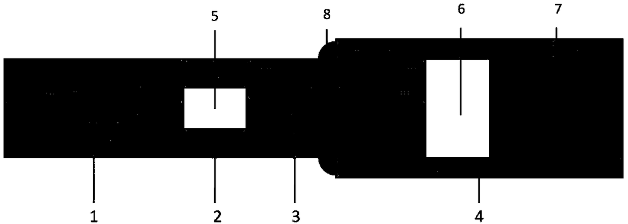
[0043] The optical fiber temperature sensing probe provided by the present invention, such as figure 1 As shown, it includes: a first single-mode fiber 1, a hollow-core fiber 2, a second single-mode fiber 3, a ceramic ferrule 4, and an ultraviolet glue 7;

[0044] One end of the hollow fiber 2 is fusion spliced ​​with one end of the first single-mode fiber 1, and the other end of the hollow fiber 2 is fu...


PUM

PropertyMeasurementUnit
lengthaaaaaaaaaa
lengthaaaaaaaaaa

Abstract

The invention discloses an optical fiber temperature sensing probe and a demodulation method. The optical fiber temperature sensing probe includes a first single-mode optical fiber, a hollow optical fiber, a second single-mode optical fiber, a ceramic ferrule and ultraviolet glue. One end of the hollow optical fiber is fused together with one end of the first single-mode optical fiber and the other end of the hollow optical fiber is fused together with one end of a second single-mode optical fiber, so that a reference Fabry-Perot interferometer. The other end of the second single-mode opticalfiber is inserted into one end of the ceramic ferrule. The ultraviolet glue is filled into the other end of the ceramic ferrule and is in the ceramic ferrule. The end face of the other end of the second single-mode optical fiber is spaced from the end face of the ultraviolet glue, so that a sensing Fabry-Perot interferometer is formed. The reference Fabry-Perot interferometer and the sensing Fabry-Perot interferometer are in cascaded connection so as to form a vernier effect, so that temperature detection flexibility is improved. According to the invention, the optical fiber temperature sensing probe is simple in manufacture method and low in manufacture cost and the temperature detection flexibility is improved.

Description

Technical field [0001] The invention belongs to the technical field of optical fiber sensing, and more specifically, relates to an optical fiber temperature sensing probe and a demodulation method. Background technique [0002] Optical fibers are widely used in the sensing field due to their small size, light weight, corrosion resistance, and strong electromagnetic interference resistance. Temperature detection is an important application field of optical fiber sensing technology. Compared with traditional electronic temperature sensors, optical fiber temperature sensors can be more widely used in specific fields such as aerospace, nuclear test research, and biomedicine. [0003] Because the thermo-optical coefficient and thermal expansion coefficient of the optical fiber itself are not large, the sensitivity of optical fiber temperature sensors is generally not high. For example, optical fiber temperature sensors based on gratings (including Bragg gratings and long-period grating...

Claims


Application Information

Patent Timeline
Patent Type & Authority Applications(China)
IPC IPC(8): G01K11/32
CPCG01K11/32
Inventor 鲁平张津刘德明
Owner HUAZHONG UNIV OF SCI & TECH
Why Eureka
Try Eureka