Backlight illumination structure based on double-sided light-dimming light guide plate and manufacturing method of backlight illumination structure

A technology for backlight illumination and light guide plate, applied in the direction of plane/plate light guide, light guide, light guide of lighting system, etc., can solve the problems of unpackaged quantum dots and complex structure, so as to improve market competitiveness, simplify device structure, The effect of reducing thickness and volume

Active Publication Date: 2018-11-20
FUZHOU UNIVERSITY
View PDF1 Cites 13 Cited by
  • Summary
  • Abstract
  • Description
  • Claims
  • Application Information

AI Technical Summary

Problems solved by technology

In CN104566015A, a method for making quantum dots on the surface of the light guide plate is proposed, which can improve the utilization rate of light and increa

Method used


Image

  • Backlight illumination structure based on double-sided light-dimming light guide plate and manufacturing method of backlight illumination structure
  • Backlight illumination structure based on double-sided light-dimming light guide plate and manufacturing method of backlight illumination structure
  • Backlight illumination structure based on double-sided light-dimming light guide plate and manufacturing method of backlight illumination structure

Examples


Example Embodiment

[0035] Example 1

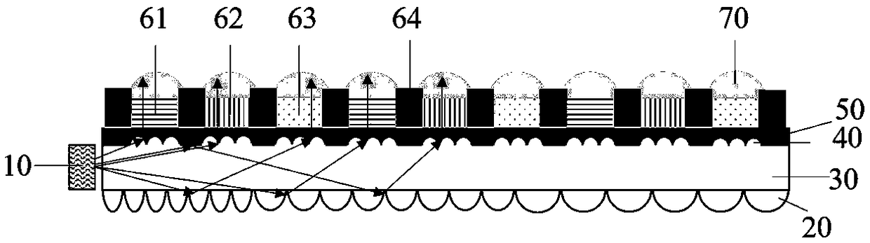
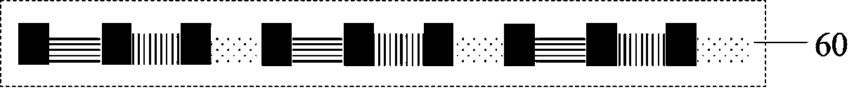
[0036] Such as figure 1 As shown, 10 is a blue LED dot matrix backlight, the light source interval is 5 mm, the light source wavelength is 365nm, 20 is a scattering microstructure, 30 is an edge light guide plate, 40 is a collimating microstructure, and 50 is a substrate light guide layer. 60 is a quantum dot color film layer, 61 and 62 are quantum dot red and green pixel units, 63 is an empty pixel unit, 64 is a black matrix, and 70 is a convex lens focusing microstructure. The scattering microstructure on the lower surface of the light guide plate and the collimating microstructure on the upper surface are designed, and the radius of curvature of the scattering microstructure near the light entrance side is 10e -5 m, the radius of curvature of the side away from the light incident becomes larger and larger, and becomes larger according to a certain rule; the radius of curvature of the collimated microstructure is 5e -5 m, and make positioning marks to accurate...

Example Embodiment

[0038] Example 2

[0039] Such as Figure 4 As shown, 10 is a blue LED dot matrix backlight, the light source interval is 5 mm, the light source wavelength is 365nm, 20 is a scattering microstructure, 30 is an edge-type light guide plate, 40 is a collimating microstructure, and 50 is a substrate light guide layer. 60 is a quantum dot color film layer, 61 and 62 are quantum dot red and green pixel units, 63 is an empty pixel unit, 64 is a black matrix, and 71 is a convex lens focusing microstructure. The scattering microstructure on the lower surface of the light guide plate and the collimating microstructure on the upper surface are designed, and the radius of curvature of the scattering microstructure near the light entrance side is 12e -5 m, the radius of curvature of the side away from the light incident becomes larger and larger, and becomes larger according to a certain rule; the radius of curvature of the collimated microstructure is 6e -5 m, and make positioning marks to ac...

Example Embodiment

[0040] Example 3

[0041] Such as Figure 5 As shown, 10 is a blue LED dot matrix backlight, the light source interval is 5 mm, the light source wavelength is 365nm, 20 is a scattering microstructure, 30 is an edge-type light guide plate, 40 is a collimating microstructure, and 50 is a substrate light guide layer. 65 is a quantum dot light conversion film, 72 is a convex lens condensing microstructure, 81, 82, and 83 are three primary color filters of red, green and blue, and 84 is a black matrix. The scattering microstructure on the lower surface of the light guide plate and the collimating microstructure on the upper surface are designed, and the radius of curvature of the scattering microstructure near the light entrance side is 12e -5 m, the radius of curvature of the side away from the light incident becomes larger and smaller, and the radius of curvature of the collimated microstructure is 6e -5 m, and make positioning marks to accurately align with the subsequent sub-pixel...


PUM

PropertyMeasurementUnit
Center wavelengthaaaaaaaaaa
Half widthaaaaaaaaaa
Thicknessaaaaaaaaaa

Abstract

The invention relates to a backlight illumination structure based on a double-sided light-dimming light guide plate and a manufacturing method of backlight illumination structure. The illumination structure comprises a side-entry type light source, a light guide plate, a base plate light-guiding layer, a quantum dot colored film layer and a spot light micro-structure, wherein the side-entry type light source, the light guide plate, the base plate light-guiding layer, the quantum dot colored film layer and the spot light micro-structure are sequentially arranged; a colored light filter in a liquid crystal panel is moved into backlight through the backlight structure, and is combined with a light-dimming scattering micro-structure of a scattering layer so as to perform light dimming; due tolight extraction of the light-guiding layer and light modulation of the micro-structure, the phenomenon that the structure has uniform light output is ensured simultaneously, optical film plates are integrated, so that the size and the thickness of the device are reduced, the device structure is simplified, and light energy can be fully and effectively utilized; by utilizing the design including the size, the position and the like of the micro-structure in the backlight, color adjustment is directly carried out, light dimming of a pixel array micro-structure is realized on the backlight, and the backlight illumination structure has the characteristics of simplicity, integration and the like; moreover, the luminous efficacy can be greatly enhanced, the purity of the color and the color domain are promoted, and the market competitiveness of liquid crystal display is greatly improved.

Description

technical field [0001] The invention relates to the fields of high-density sub-pixel display technology, backlight source and lighting, and in particular to a backlight lighting structure based on a double-sided dimming light guide plate and a manufacturing method thereof. Background technique [0002] At present, liquid crystal display is the most popular display on the market. It has the advantages of low driving voltage, low power consumption, large amount of displayed information, high resolution, easy colorization, long life, and no radiation pollution. It is widely used in smart phones. Mobile phones, tablets, computers, large-screen TVs and data projectors, etc. [0003] The traditional liquid crystal display structure consists of a backlight module and a liquid crystal panel. The light emitted by the backlight passes through structures such as reflectors, light guide plates, diffusion films, and prism films, and then enters the liquid crystal panel through polarizers...

Claims


Application Information

Patent Timeline
IPC IPC(8): G02F1/13357G02F1/1335G02B6/00
CPCG02B6/004G02F1/133512G02F1/133514G02F1/133615G02F1/133614
Inventor 陈恩果林淑颜徐胜叶芸郭太良林金堂缪煌辉江宗钊
Owner FUZHOU UNIVERSITY
Why Eureka
Try Eureka