Laser radar

A laser radar and laser technology, applied in the field of radar, can solve the problems of reducing the heat dissipation effect of the laser emission board, low space utilization, complex process, etc., to avoid local high temperature burning components, improve heat dissipation efficiency and performance, and flexible structural design. Effect

Active Publication Date: 2018-11-23
HESAI TECH CO LTD
View PDF6 Cites 9 Cited by
  • Summary
  • Abstract
  • Description
  • Claims
  • Application Information

AI Technical Summary

Problems solved by technology

[0005] 1) The more columns, the more difficult the production and adjustment, the more complicated the process, and the lower the production efficiency;
[0006] 2) The space utilization rate in the system is low, the focal plane is particularly crowded, and the heat is generated so much that it is difficult to export the heat, while there are few devices in other places and less heat generation;
[0007] 3) Due to the angle encryption and the increase in the number of lines achieved through multiple columns, there are also different angles in the horizontal direction between different columns. Such a beam distribution will cause image distortion of the lidar for close-range fast-moving objects;
[0008] 4) Multiple columns of lasers at the transmitting end lead to multiple columns of detectors at the receiving end, which in turn makes it difficult to isolate ambient light through apertures and other methods when ambient stray light enters the radar optical path, and ambient light noise leads to a decline in ranging capability
[0009] On the other hand, due to the extremely high positioning accuracy required by the laser emitting board for the mechanical rotary laser radar currently on the market, traditional machined parts cannot be guaranteed, and the position can only be adjusted through external auxiliary fixtures. After positioning, it cannot fully contact the heat conducting material. Bonding can only be fixed by glue, and the thermal conductivity of glue is extremely poor, which greatly reduces the heat dissipation effect of the laser emitting board
And the heat dissipation path of the prior art is that the heat of the laser emitting board is transferred to the fixed bracket of the circuit board through the glue, and then to the rotor, and the rotor and the internal air convect to dissipate heat
The thermal conductivity of the glue is poor, the heat dissipation path is long, and the heat dissipation effect is poor

Method used


Image

  • Laser radar
  • Laser radar
  • Laser radar

Examples


Embodiment 1

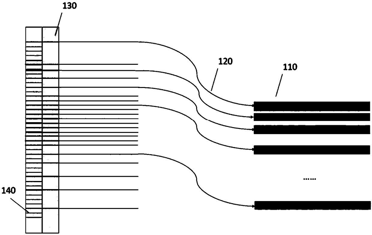
[0070] In a possible embodiment, a light emitting angle control device is provided, such as figure 1 As shown, the device includes a laser light source 110 , a first number of outgoing optical fibers 120 , and an optical fiber holder 130 . The laser beam emitted by the laser light source 110 is coupled to the outgoing optical fiber 120 .

[0071] The fiber holder 130 has a first surface on which a second number of fiber fixing grooves 140 are arranged, and the outgoing optical fiber 120 is fixed in the fiber fixing grooves 140 and passes through the first surface , and the outgoing end face of the outgoing optical fiber 120 passes through the optical fiber fixing groove 140 .

[0072] The outgoing end face of the outgoing optical fiber 120 and the fiber fixing groove 140 are configured to converge the light beam exiting the optical fiber end face according to a specified angle.

[0073] The laser light source 110 is a laser emitting board equipped with multiple lasers, and t...

Embodiment 2

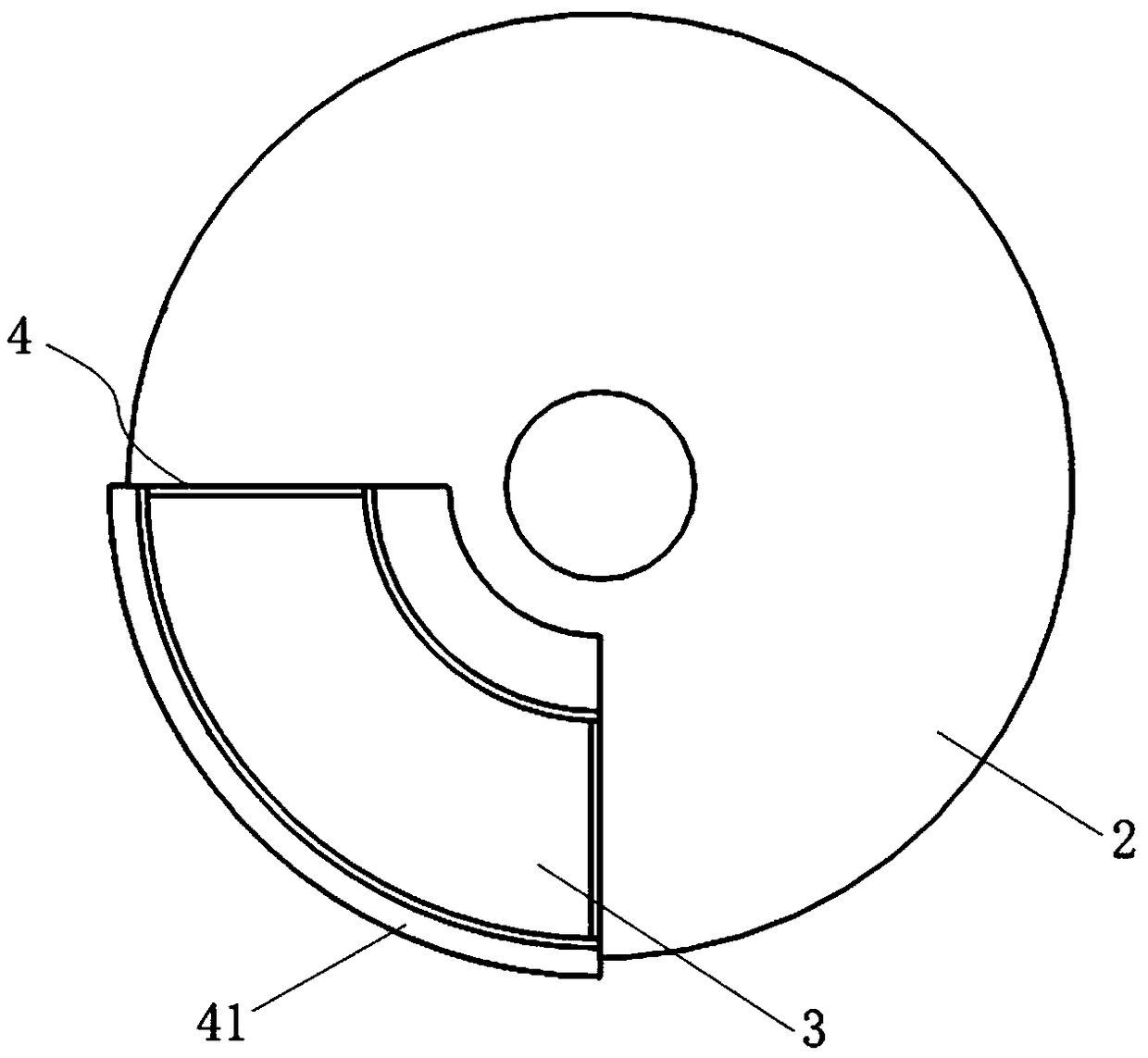
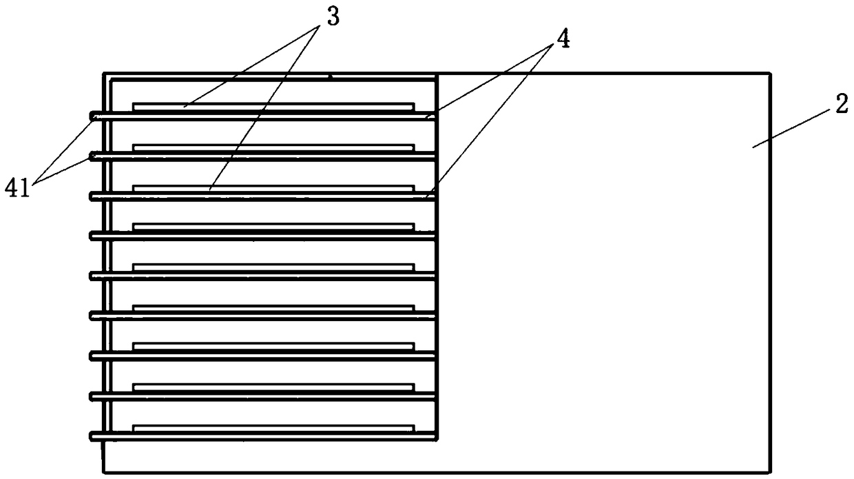
[0105] combine figure 2 , image 3 as well as Figure 20 to Figure 22 , a high-line-number laser radar, including a rotor, a laser emitting device, and an exit lens group,

[0106] The rotor has an emitting cavity and a receiving cavity isolated from each other;

[0107] The laser emitting device is used to emit detection light to the target object;

[0108] The outgoing lens group is used to emit the received detection light to the detection area;

[0109] The laser emitting device includes at least one laser emitting board 3 and a coupling optical fiber, the laser emitting board 3 is arranged in the emitting cavity, and at least one light source for emitting detection light is installed on the laser emitting board 3, so The coupling optical fiber corresponds to the light source one by one, the light source is coupled to the input end of the coupling optical fiber, and the output end of the coupling optical fiber is arranged at the focal plane of the outgoing lens assemb...


PUM


Abstract

The invention provides a lase radar. That lase radar comprises a laser light source and a laser emission optical system. The laser light source is a distributed emission light source. The distributedemission light source comprises a laser, a coupling optical fiber and an optical fiber fixture. The laser is used for emitting detection light. One end of the coupling optical fiber is coupled with the laser, and the other end is a light emergent end face. The optical fiber fixture is used for fixing the light emergent end face, and the optical fiber fixture is co-arranged with the light emergentend face of the coupling optical fiber so as to control the light emergent direction of the light emergent end face. The light emitted from the light emergent end face is incident to the laser emission optical system. According to the lase radar, the lase circuit is arranged at any position where the space is easy to dissipate heat by virtue of the flexible characteristics of the optical fiber, and the optical fiber is pulled out and arranged on the focal plane so that the luminous area and the heating area of the laser radar are separated and the structural design of the laser radar is more flexible.

Description

technical field [0001] The invention relates to the field of radar, in particular to a laser radar. Background technique [0002] Obstacle detection in the driving environment of unmanned vehicles is one of the key technologies of the autonomous navigation system of unmanned vehicles. The detection of obstacles based on lidar sensors is the most important method. The detection of obstacles based on lidar sensors is an active detection method, which is also called contact type. The detection methods mainly include methods based on lidar, millimeter-wave radar, and sonar. Lidar emits light through a rotating mirror, and measures the distance by measuring the time interval between the emitted light and the reflected light. The laser has good monochromaticity, high brightness, high bit accuracy, and high resolution, which is beneficial to overcome the interference of ground clutter, high sensitivity, and is not affected by light, especially in dark environments. Based on thes...

Claims


Application Information

Patent Timeline
Patent Type & Authority Applications(China)
IPC IPC(8): G01S7/481G02B6/08
CPCG01S7/4818G02B6/08G01S7/4817G01S17/931
Inventor 王瑞朱雪洲李娜李家盛王红光向少卿李一帆
Owner HESAI TECH CO LTD
Why Eureka
Try Eureka