
Collimator and manufacturing method

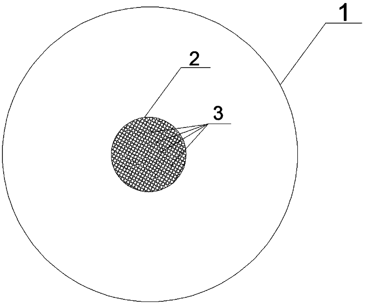
A collimator and substrate technology, applied in the direction of using aperture/collimator, glass manufacturing equipment, manufacturing tools, etc., can solve the problems of limited drilling preparation methods, difficult control of particle movement speed, and unachievable diameter , to achieve the effect of solving the problem of size uniformity and high precision, solving the problem of reliability and stability, and easy to control the accuracy of size

Active Publication Date: 2018-11-30
CHINA BUILDING MATERIALS ACAD
View PDF9 Cites 6 Cited by
  • Summary
  • Abstract
  • Description
  • Claims
  • Application Information

AI Technical Summary

Problems solved by technology

However, the single-hole collimator currently used is bulky, and it is difficult to accurately control the particle scattering angle, and the movement speed of the particles in the hole is not easy to control, resulting in a low particle collimation rate and ultimately resulting in extremely low particle utilization.
In addition, limited by the preparation method of the hole, the diameter of the through-hole of the single-hole collimator cannot be micron or below, which affects the collimation efficiency and utilization of the particles
In reports, metal porous collimators are also used as components of the particle collimation system, but the reliability of the materials used is poor, especially the precision of the through hole size is low, the structure uniformity is poor, and it is difficult to provide a stable particle beam. Poor straightening effect, resulting in short service life of the device and low collimation rate

Method used


Image

  • Collimator and manufacturing method
  • Collimator and manufacturing method
  • Collimator and manufacturing method

Examples


preparation example Construction

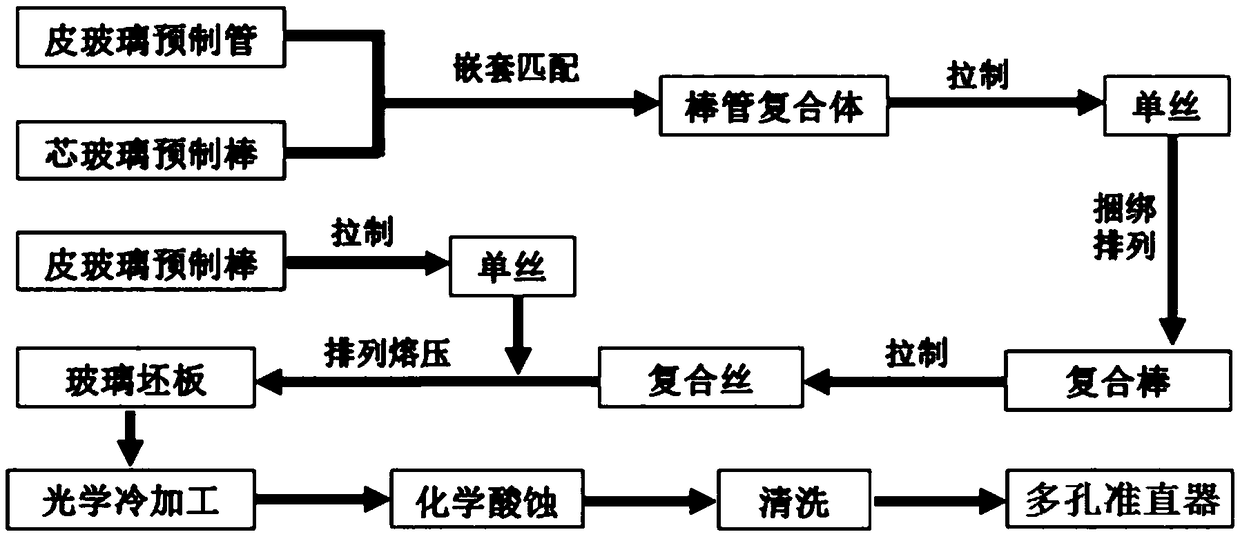
[0118] Adopting the glass rod tube nested drawing method, the preparation method of the collimator comprises the following steps:

[0119] (1) prepare skin glass and core glass respectively, through high temperature melting and clarification, obtain uniform skin glass melt and core glass melt respectively;

[0120] (2) The skin glass melt is mechanically drawn to form a skin prefabricated tube, the skin glass melt is formed into a skin preform through leakage, and the core glass melt is formed into a core preform through leakage;

[0121] (3) Nesting the skin prefabricated tube and the core prefabricated rod to form a tube-rod complex, drawing the tube-rod complex to form a monofilament of the tube-rod complex;

[0122] (4) Arranging the monofilaments of the tube-rod complex, binding them to obtain composite rods, and then drawing them to form composite filaments;

[0123] (5) drawing the skin preform to form a monofilament of the skin preform;

[0124] (6) Arranging the mon...

Embodiment 1

[0224] The collimator in this embodiment has a good match with tungsten material and glass material with similar expansion coefficient.

[0225] The preparation method of the collimator adopts a glass rod tube nested drawing method, comprising the following steps:

[0226] (1) prepare skin glass and core glass respectively:

[0227] Leather glass selection medium expansion glass, in terms of mass percentage, including: SiO 2 : 69.0%, B 2 o 3 : 23.5%, Al 2 o 3 : 3.0%, Li 2 O: 1.5%, Na 2 O: 2.0%, ZrO 2 : 1.0%, its expansion coefficient is 41×10 -7 / °C;

[0228] Core glass corresponding to skin glass, in mass percentage, including: B 2 o 3 : 44.0%, La 2 o 3 : 24.0%, SiO 2 : 23.5%, Al 2 o 3 : 3.5%, Na 2 O: 3.0%, K 2 O: 2.0%, its expansion coefficient is 55×10 -7 / °C;

[0229] (2) The skin glass is formed into a skin prefabricated tube by mechanical drawing. The inner diameter of the skin prefabricated tube is controlled at (32±0.5) mm, and the wall thickness of...

Embodiment 2

[0238] The collimator in this embodiment has a good match with stainless steel material or glass material with similar expansion coefficient.

[0239] The preparation method of the collimator adopts a glass rod tube nested drawing method, comprising the following steps:

[0240] (1) prepare skin glass and core glass respectively:

[0241] Leather glass chooses high-expansion glass, in terms of mass percentage, including: SiO 2 : 63.0%, B 2 o 3 : 4.5%, Al 2 o 3 : 1.0%, BaO: 8.0%, CaO: 4.5%, MgO: 3.0%, Na 2 O: 10.0%, K 2 O: 5.0%, ZrO 2 : 1.0%; its expansion coefficient is 92×10 -7 / °C;

[0242] Core glass corresponding to skin glass, in mass percentage, including: B 2 o 3 : 31.0%, BaO: 21.0%, La 2 o 3 : 28.0%, SiO 2 : 10.0%, Al 2 o 3 : 1.0%, Na 2 O: 5.0%, K 2 O: 4.0%, its expansion coefficient is 102×10 -7 / °C;

[0243] (2) The skin glass is formed into a skin prefabricated tube by mechanical drawing. The inner diameter of the skin prefabricated tube is contr...


PUM

PropertyMeasurementUnit
pore sizeaaaaaaaaaa
diameteraaaaaaaaaa
thicknessaaaaaaaaaa

Abstract

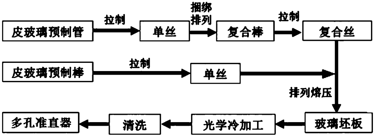
The invention relates to a collimator and a manufacturing method. The collimator includes a base body of a flat plate shape, wherein the upper surface and lower surface of the base body are parallel to each other, at least a through hole which penetrates through the upper surface and the lower surface and has a pore diameter of 1-100 [mu]m is formed in the base body, and the base body is made of glass. A glass blank plate is prepared by using a glass rod tube nested drawing method, optical cold processing is conducted, and then chemical etching is performed so as to obtain the collimator. After the glass of the collimator is determined, core glass matched with the determined glass is designed, and the core glass is removed through acid etching, wherein the core glass is mainly used as a filling material of micropores during manufacture so as to ensure the roundness of the micropores. Through the collimator, the collimation efficiency of particles and stability of particle movement canbe improved effectively, the scattering angle of the particles is reduced, and conditions for high stability, high reliability and miniaturization of atomic clocks, ray cameras and other precision equipment are created.

Description

technical field [0001] The invention belongs to the technical field of preparation of inorganic non-metallic materials, and in particular relates to a collimator and a preparation method. Background technique [0002] In some precision instruments, medical devices and electronic devices, the collimated motion of atoms, electrons, ions, molecules and other particles has significantly affected the stability, reliability and service life of the devices. The collimated particle motion can form a particle beam with a small scattering angle, which is conducive to the formation of a stable and long-lasting gas flow or liquid flow, thereby providing a highly stable signal source or a gas and liquid particle beam for related devices. Therefore, the collimation rate of particles can determine the performance of the device to a certain extent. [0003] As the core component of the particle collimation system, the collimator is responsible for the key role of particle collimation and e...

Claims


Application Information

Patent Timeline
Patent Type & Authority Applications(China)
IPC IPC(8): G21K1/02C03B37/027C03B37/14C03C3/089C03C3/091C03C3/093C03C15/00
CPCC03B37/027C03B37/14C03C3/089C03C3/091C03C3/093C03C15/00G21K1/02
Inventor 黄永刚贾金升王久旺周游王云付杨张洋薄铁柱
Owner CHINA BUILDING MATERIALS ACAD
Learn More