Formation method and structure of igbt device
A device and cell technology, applied in the field of IGBT device formation methods and structures, can solve problems such as increased capacitance, and achieve the effects of improving on-state voltage drop, increasing process window, and improving capacitance Cgc
- Summary
- Abstract
- Description
- Claims
- Application Information
AI Technical Summary
Problems solved by technology
Method used
Image
Examples
Embodiment Construction
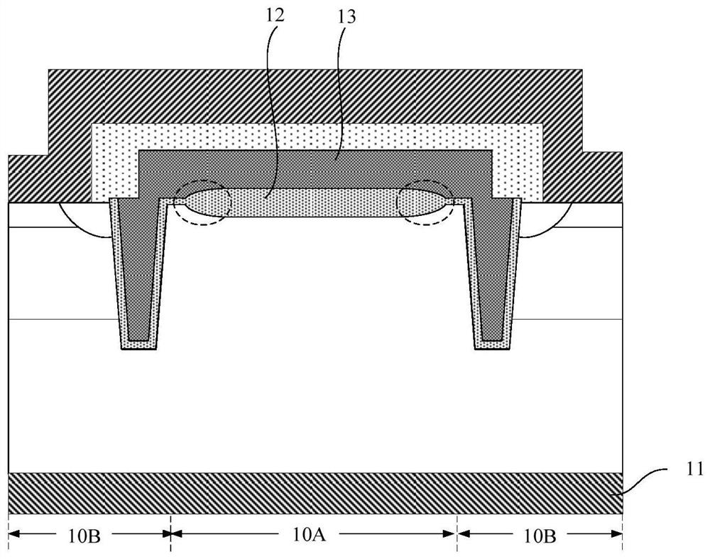
[0036] As mentioned in the background art, in trench type IGBT devices, a redundant cell (dummy cell) is formed between multiple functional cells to reduce the channel density, thereby improving the short-circuit resistance of the IGBT device. question. However, this method will correspondingly cause the capacitance Cgc between the gate and the collector to increase, thereby affecting the overall performance of the device.
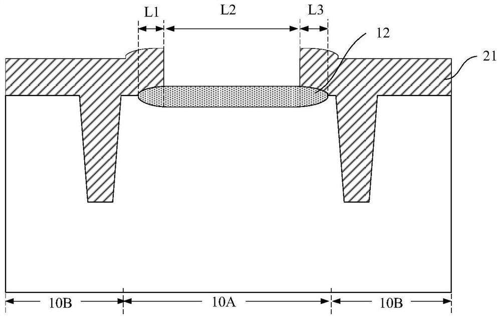
[0037] In order to improve the capacitance Cgc between the gate and the collector, it is generally necessary to form a thick dielectric layer between the gate and the collector in the redundant cells. figure 1 is a structural schematic diagram of an IGBT device, such as figure 1 As shown, the IGBT device has a plurality of functional cells 10B and a redundant cell 10A between the plurality of functional cells 10B, and the redundant cell 10A includes a collector 11, a dielectric layer 12 and a Gate electrode 13. Wherein, the dielectric layer 12 can be fo...
PUM
| Property | Measurement | Unit |
|---|---|---|
| size | aaaaa | aaaaa |
Abstract
Description
Claims
Application Information
 - R&D
- Intellectual Property
- Life Sciences
- Materials
- Tech Scout
- Unparalleled Data Quality
- Higher Quality Content
- 60% Fewer Hallucinations
Browse by: Latest US Patents, China's latest patents, Technical Efficacy Thesaurus, Application Domain, Technology Topic, Popular Technical Reports.
© 2025 PatSnap. All rights reserved.Legal|Privacy policy|Modern Slavery Act Transparency Statement|Sitemap|About US| Contact US: help@patsnap.com


