Switch cabinet condensation prevention device

A technology for anti-condensation and switchgear, which is applied in the substation/power distribution device casing, anti-corrosion coating, coating, etc., can solve the problems of accelerated aging of equipment in the cabinet, achieve excellent mechanical properties and insulation properties, simple synthesis, and enhanced The effect of stability

Active Publication Date: 2018-12-07
NANYANG POWER SUPPLY COMPANY OF STATE GRID HENAN ELECTRIC POWER
View PDF12 Cites 3 Cited by
  • Summary
  • Abstract
  • Description
  • Claims
  • Application Information

AI Technical Summary

Problems solved by technology

And if the temperature in the cabinet is too high for a long time, it will accelerate the aging of the equipment in the cabinet.

Method used


Image

  • Switch cabinet condensation prevention device
  • Switch cabinet condensation prevention device
  • Switch cabinet condensation prevention device

Examples


Embodiment 1

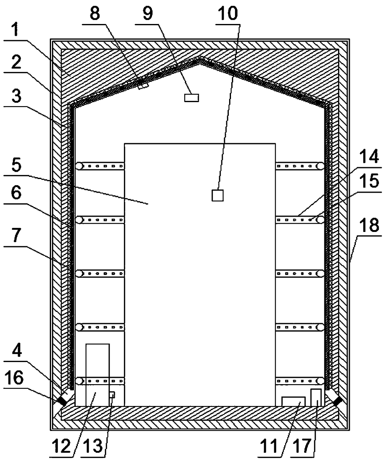
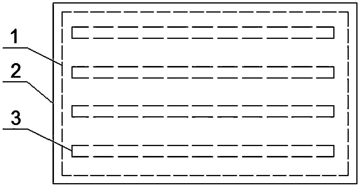
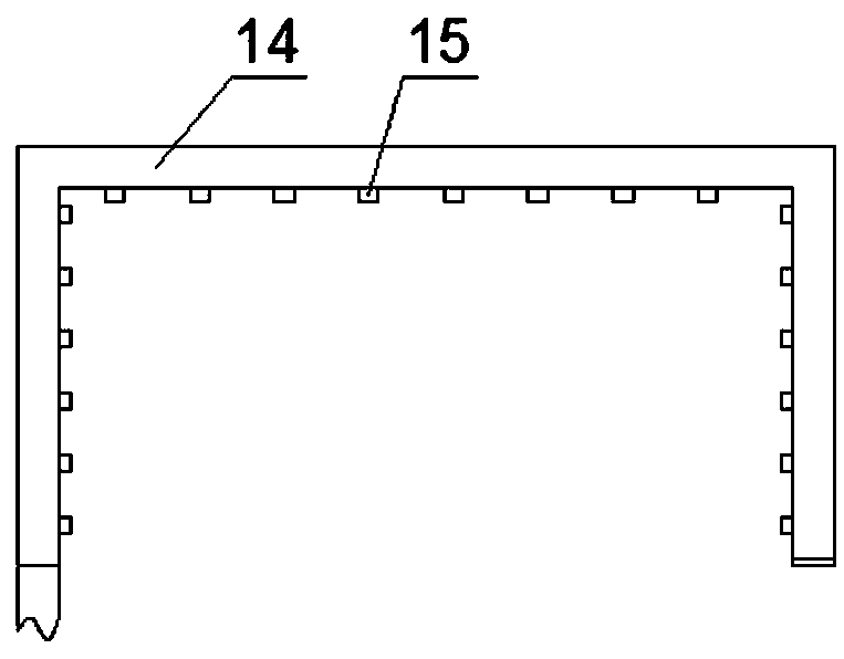
[0034] Such as figure 1 , figure 2 and image 3 As shown, a switch cabinet anti-condensation device includes a cabinet body 1, the outer surface of the cabinet body 1 is provided with an insulation layer 2, the inner top of the cabinet body 1 is tapered, and the inner wall of the cabinet body 1 is vertically A plurality of grooves 3 are provided in the vertical direction, and inclined drainage holes 4 are provided at the lower part of the cabinet body 1 corresponding to the two lower ends of the grooves 3, and the grooves 3 are provided with a The cold iron bars 6 that describe the surface temperature of the electrical equipment 5 in the cabinet 1, the two lower ends of the cold iron bars 6 are respectively located at the upper ends of the corresponding drain holes 4, the gap between the cold iron bars 6 and the groove 3 A semiconductor cooling chip 7 for cooling the cold iron bars 6 is arranged between them, a first temperature sensor 8 is arranged on the inner wall of the...

Embodiment 2

[0045] The difference from Example 1 is that the waterproof layer contains components and their contents: 16 parts by weight of polyaniline, 2.5 parts by weight of polymethyl methacrylate, 7 parts by weight of chloroform, N,N-di 42 parts by weight of methyl formamide, 16 parts by weight of sodium silicate, 2.8 parts by weight of sodium lauryl sulfate, 8 parts by weight of nano silicon dioxide, 6 parts by weight of sodium methyl silicate, tetrachloroterephthalic acid di 3.7 parts by weight of methyl ester, 8.9 parts by weight of cinnamaldehyde, 23 parts by weight of acetone, and 48 parts by weight of deionized water.

Embodiment 3

[0047] The difference from Example 1 is that the waterproof layer contains components and their contents: 17 parts by weight of polyaniline, 3 parts by weight of polymethyl methacrylate, 7.5 parts by weight of chloroform, N,N-di 44 parts by weight of methyl formamide, 16.5 parts by weight of sodium silicate, 3 parts by weight of sodium lauryl sulfate, 9 parts by weight of nano silicon dioxide, 6.1 parts by weight of calcium stearate, dimethyl tetrachloroterephthalate 3.9 parts by weight of ester, 9 parts by weight of polyaspartic acid, 24 parts by weight of acetone, and 50 parts by weight of deionized water.


PUM

PropertyMeasurementUnit
thicknessaaaaaaaaaa
tensile strengthaaaaaaaaaa
elongation at breakaaaaaaaaaa

Abstract

The invention discloses a switch cabinet condensation prevention device comprising a cabinet body. The outer surface of the cabinet body is provided with a heat preservation layer. The top of the inner side of the cabinet body is conical, and the inner wall of the cabinet body is provided with multiple grooves along the vertical direction. The lower part of the cabinet body is provided with inclined drain holes. The grooves are internally provided with cold iron bars. Semiconductor refrigeration sheets are arranged between the cold iron bars and the grooves. The inner wall of the cabinet bodyis provided with a first temperature sensor. The cabinet body is internally provided with a dew point instrument which is used for detecting the inner air temperature. The outer surface of the electrical equipment in the cabinet body is provided with a second temperature sensor. The cabinet body is internally provided with a drying mechanism which is used for drying the electrical equipment. The cold iron bars of which the temperature is lower than that of the surface of the electrical equipment in the switch cabinet can be provided and the condensation phenomenon is enabled to occur on the surface of the cold iron bars by priority so that the probability of condensation on the electrical equipment in the switch cabinet can be greatly reduced; besides, the electrical equipment can be driedby using the drying mechanism in the cabinet body so as to further avoid the condensation phenomenon on the electrical equipment.

Description

technical field [0001] The invention relates to the technical field of anti-condensation for switch cabinets, in particular to an anti-condensation device for switch cabinets. Background technique [0002] The switchgear is a very important electrical equipment in the power system. In the power system, the switchgear is responsible for the dual functions of closing and disconnecting the power line and protecting the safety of the system. With the rapid development of electric power towards high voltage, large units, and large capacity, the growing power grid and the popularization and promotion of substation unattended management mode and comprehensive automation, the safe operation of switchgear is becoming more and more important, and the modern power system has a great impact on power quality. The requirements are getting higher and higher, and correspondingly higher requirements are put forward for the reliability of the switchgear. [0003] Due to the narrow space in t...

Claims


Application Information

Patent Timeline
Patent Type & Authority Applications(China)
IPC IPC(8): H02B1/28C09D179/02C09D133/12C09D7/61C09D7/63C09D7/65C09D5/08C09D7/20
CPCH02B1/28C09D7/63C09D7/65C09D179/02C09D5/08C09D7/20C09D7/61C08K2201/011C08L33/12C08K13/02C08K3/34C08K3/36C08K5/41
Inventor 薛宇罗道军华大鹏沙淼
Owner NANYANG POWER SUPPLY COMPANY OF STATE GRID HENAN ELECTRIC POWER
Why Eureka
Try Eureka