High-efficiency power generation system based on waste heat of tank calciner based on mother tube

A tank-type calciner and power generation system technology, which is applied in the field of waste heat utilization in the carbon industry, can solve the problems of high-power blower carbon production costs, waste of waste heat resources in flue gas, and inactive waste heat recovery, etc., to achieve reduction of purchased electricity, Small footprint and reduced production costs

Active Publication Date: 2020-11-10
HUATIAN NANJING ENG & TECH CORP MCC
View PDF6 Cites 0 Cited by
  • Summary
  • Abstract
  • Description
  • Claims
  • Application Information

AI Technical Summary

Problems solved by technology

However, due to the obvious characteristics of the flue gas from the calciner, that is, the flue gas temperature is high, but the flue gas volume is small, which makes the carbon plant not very active in recovering the waste heat of the high-temperature flue gas from the calciner, and many carbon plants even use blast The way of cooling is to mix low-temperature air into high-temperature flue gas through a high-power blower, perform forced cooling and then discharge it into the atmosphere, resulting in waste of valuable waste heat resources of the flue gas, and the new power consumption of the high-power blower also brings carbon increase in production costs
[0005] In addition, the high-temperature calcined coke (temperature up to 1000°C) at the outlet of the pot calciner also contains a large amount of sensible heat. The current method is to install a cooling water jacket under the calciner, and cool the high temperature by circulating cooling water. The calcined coke is cooled, and the cooling water in the cooling water jacket exchanges heat indirectly with the calcined coke of the calciner. The cooling water after absorbing heat is sent to the cooling tower to dissipate heat, and then returns to the water jacket to be used as a cooling water jacket to feed water, so cycle, obviously, this way leads to a lot of waste of heat energy

Method used


Image

  • High-efficiency power generation system based on waste heat of tank calciner based on mother tube

Examples


Embodiment Construction

[0018] The following will describe the embodiment of the high-efficiency waste heat power generation system of tank-type calciner based on the main pipe according to the present invention with reference to the accompanying drawings. Those skilled in the art would recognize that the described embodiments can be modified in various ways or combinations thereof without departing from the spirit and scope of the invention. Accordingly, the drawings and description are illustrative in nature and not intended to limit the scope of the claims. Also, in this specification, the drawings are not drawn to scale, and like reference numerals denote like parts.

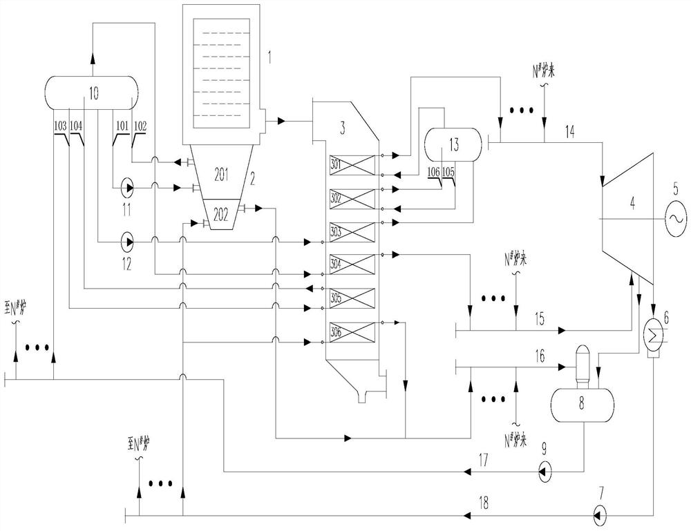
[0019] The waste heat high-efficiency power generation system of tank-type calciner based on parent control includes at least one set of waste heat power generation sub-system, and any waste heat power generation sub-system includes at least tank-type calciner 1, calcined coke cooling device 2, waste heat boiler 3, and low-pressure...


PUM


Abstract

An efficient pot calcinator waste heat power generating system based on header pipes comprises a turbine, a generator, a deaerator, the high-pressure steam header pipe, the low-pressure steam header pipe, the deaerator water inlet header pipe, the low-pressure water feeding header pipe, a low-pressure water feeding pump and at least one set of waste heat power generation subsystem. Steam outlets of all high-pressure superheaters communicate with a main steam opening of the turbine through the high-pressure steam header pipe. Steam outlets of all low-pressure superheaters communicate with a steam supplementing opening of the turbine through the low-pressure steam header pipe. The turbine pulls the generator to generate power. In any one waste heat power generation subsystem, a low-pressuresteam water circulation loop is formed between a low-pressure boiler barrel and a calcined coke evaporative cooling module; and a low-pressure steam water circulation loop is formed between the low-pressure boiler barrel and a low-pressure evaporator, and a high-pressure steam water circulation loop is formed between a high-pressure boiler barrel and a high-pressure evaporator. According to the efficient pot calcinator waste heat power generating system, the calcined coke waste heat is recovered and used, the layout is compact, and the investment cost is low. The resource utilization rate of acalcination process is increased, the outsourcing electric quantity is reduced for a carbon factory, and the production cost is reduced for the carbon factory.

Description

technical field [0001] The invention relates to the technical field of waste heat utilization in the carbon industry, in particular to a high-efficiency power generation system for waste heat of a tank-type calciner based on a mother pipe. Background technique [0002] Carbon material is one of the main raw materials in the electrolytic aluminum production process, and the production of carbon material products is a key link that restricts the development of the aluminum industry. In recent years, the development of my country's aluminum industry has entered a fast track, and carbon for aluminum has developed accordingly. The production capacity of carbon material products has increased from a few million tons a few years ago to the current tens of millions of tons, and it is still developing at a certain growth rate. [0003] The pot calciner is one of the main equipments in the carbon production process. It can calcinate petroleum coke with different volatile content. It h...

Claims


Application Information

Patent Timeline
Patent Type & Authority Patents(China)
IPC IPC(8): F01K27/00F01K11/02F01D15/10F27D17/00F22B1/18F22D1/50
CPCF01D15/10F01K11/02F01K27/00F22B1/1807F22D1/50F27D17/004Y02E20/30Y02P10/25Y02P80/10Y02P80/15
Inventor 江文豪
Owner HUATIAN NANJING ENG & TECH CORP MCC
Why Eureka
Try Eureka