Microstrip series-fed linear array circularly polarized microstrip antenna

A technology of microstrip antenna and circular polarization, applied in the direction of antenna, antenna coupling, antenna components, etc., can solve the problems of complex feeding circuit, complicated processing process, inconvenient integration, etc., and achieve simple feeding system and radiation axis ratio Low, the effect of increasing the antenna gain

Inactive Publication Date: 2018-12-11
10TH RES INST OF CETC
View PDF3 Cites 15 Cited by
  • Summary
  • Abstract
  • Description
  • Claims
  • Application Information

AI Technical Summary

Problems solved by technology

Although the coaxial line feeding can avoid the influence of the feeder line on the performance of the antenna, the processing process is more complicated and it is not easy to integrate; the microstrip line feeding adopts the coplanarity of the feeder line and the patch, which is easy to achieve impedance matching, and the structure is simple and low in cost, suitable for miniaturization The disadvantage is that the bandwidth is narrow; the electromagnetic coupling feed uses multiple feed points to feed, which is often used to solve the feed problem of multi-layer antenna arrays, but the feed circuit is usually more complicated, the cost is higher, and the size is larger

Method used


Image

  • Microstrip series-fed linear array circularly polarized microstrip antenna
  • Microstrip series-fed linear array circularly polarized microstrip antenna
  • Microstrip series-fed linear array circularly polarized microstrip antenna

Examples


Embodiment Construction

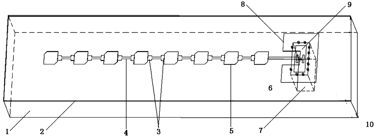
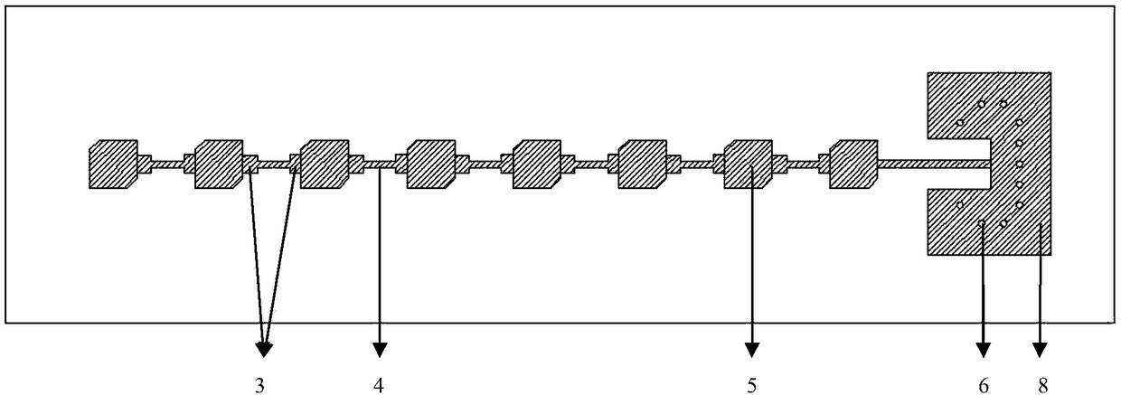
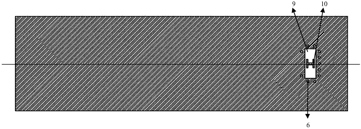
[0018] refer to Figure 1-3 . In the embodiment described below, the dielectric substrate 2 laminated on the metal plate 1 and the metal floor closely attached to the lower surface of the dielectric substrate 2 are included. The copper-clad sheet on the surface of the dielectric substrate 2 is etched into a microstrip metal radiation patch 5 connected in series with the microstrip series feeder 4 and a transition metal patch 8 with a rectangular groove connected to the end microstrip series feeder line. The metal patch 8, the microstrip metal radiation patch 5, and the microstrip serial feeder 4 are all on the upper surface of the dielectric substrate 2, and the lower surface layer of the dielectric substrate 2 is a thin metal sheet. On the surface metal floor under the dielectric substrate 2, a rectangular coupling slit 9 corresponding to the transition metal patch 8 and an H-shaped coupling patch 10 framed in the rectangular coupling slit 9 are etched, and the rectangular c...


PUM


Abstract

The invention provides a microstrip series-fed linear array circularly polarized microstrip antenna and aims to provide a high gain, low axis ratio, wide band waveguide interface microstrip series fed antenna, the invention is realized by the following technical scheme: A surface copper coating on a dielectric substrate (2) is etch into a linear array microstrip metal radiation patch (5) connected in series with a microstrip string feed line (4) and a transition metal patch (8) connected with that microstrip string feed line, a rectangular coupling slots of corresponding transition metal patch and H-shaped couple patch (10) placed into the rectangular coupling slot (9) are etched on that metal floor of the lower surface layer of the dielectric substrate (2); Metal shield hole (6) penetrating that upper and lower surface of the dielectric substrates are arranged around of the rectangular coupling gap in an enveloping manner; The metal plate (1) is provided with a waveguide cavity (7)penetrating the metal plate; The circularly polarized microstrip antenna in which the transition metal patch, a rectangular coupling slot, an H-shaped coupling patch and a metal shield hole realize the electromagnetic wave transmission between the series feeder and the waveguide interface, and a microstrip metal radiation patch realizes radiation is formed. .

Description

technical field [0001] The invention relates to a circularly polarized microstrip antenna applicable to satellite navigation, radar and other field systems, in particular to a microstrip series feeder array circularly polarized microstrip antenna applied to the V frequency band. Background technique [0002] Circularly polarized antennas have unique anti-interference performance. The so-called circular polarization means that the end point of the electric field vector moves with time at a fixed position in space. If the trajectory formed by the motion is a circle, it is called circular polarization. It can be decomposed into two linearly polarized waves, which are orthogonal to each other, have the same amplitude, but are 90° out of phase. Compared with linearly polarized antennas, circularly polarized antennas have the following advantages: (a) Any linearly polarized incoming waves can be received by circularly polarized antennas, and any linearly polarized antenna can rec...

Claims


Application Information

Patent Timeline
IPC IPC(8): H01Q1/36H01Q1/48H01Q1/50H01Q1/52
CPCH01Q1/36H01Q1/48H01Q1/50H01Q1/526
Inventor 李佳美官正涛
Owner 10TH RES INST OF CETC
Why Eureka
Try Eureka