Temperature rising and falling type sound velocity measuring instrument

A measuring instrument and heating and cooling technology, applied in the direction of measuring device, measuring propagation velocity, measuring ultrasonic/sonic wave/infrasonic wave, etc., can solve problems such as easy formation of echo, increased error rate, temperature control lag, etc., to improve accuracy and reduce Reading error rate, the effect of avoiding reading errors

Pending Publication Date: 2018-12-14
NANJING FORESTRY UNIV
View PDF7 Cites 2 Cited by
  • Summary
  • Abstract
  • Description
  • Claims
  • Application Information

AI Technical Summary

Problems solved by technology

[0005] 1. The thermal inertia of water is strong, the temperature control lags behind, and the heat of heating is easy to cool down, resulting in low accuracy of temperature control, which is not conducive to the control of experimental accuracy
[0006] 2. When the water inside the outer cavity flows, it is easy to vibrate the closed cavity, which will interfere with the experimental measurement and cause errors easily
[0007] 3. The existing airtight chamber structure is elongated, and it is easy to form echoes in the narrow and long airtight environment, which will interfere with the measurement and increase the error rate easily
[0008] 4. Since the vernier scale can only be observed through the outer cavity, the water in the outer cavity will refract light, and the visual scale is easy to cause reading errors
[0009] 5. The overall instrument adopts a closed structure, which is inconvenient for maintenance and repair

Method used


Image

  • Temperature rising and falling type sound velocity measuring instrument
  • Temperature rising and falling type sound velocity measuring instrument
  • Temperature rising and falling type sound velocity measuring instrument

Examples


Embodiment Construction

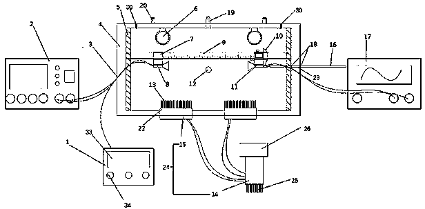
[0037] In order to make the technical solution of the present invention clearer, the present invention will be further described below in conjunction with the accompanying drawings. Any solution obtained by equivalent replacement and conventional reasoning of the technical features of the technical solution of the present invention falls within the protection scope of the present invention. The fixed connection method and fixed arrangement method not mentioned in this embodiment are one of glue, bolt and nut connection, and screw connection. The wires of the ultrasonic generating transducer and ultrasonic receiving transducer inside the plexiglass box are connected to the control panel, signal generator, and oscilloscope through wire holes. Wired to connect to the control panel.

[0038]The signal generator, the ultrasonic generation transducer and the ultrasonic receiving transducer used in this embodiment are a set of existing instruments, which are the SV-DH series sound ve...


PUM


Abstract

The invention discloses a temperature rising and falling type sound velocity measuring instrument, which comprises an organic glass box, a control panel, a signal generator, an infrared heating tube,an ultrasonic wave generating transducer, an ultrasonic wave receiving transducer, a temperature sensor and an oscilloscope, wherein a sliding rod is arranged in the organic glass box; a load bearingsheet is fixedly connected to one end of the sliding rod; the bottom of the load bearing sheet is fixedly connected with the ultrasonic wave generating transducer; a grating electronic ruler is slidably connected to the other end of the sliding rod; the ultrasonic wave receiving transducer is fixedly connected to the bottom of the grating electronic ruler; a push rod is connected to one end of thebottom of the grating electronic ruler; a plurality of semiconductor refrigerating chips are arranged at the bottom in the organic glass box; the temperature sensor is fixedly arranged at the centerof a side plate at one side of the organic glass box; and the infrared heating tube, the semiconductor refrigerating chips and the temperature sensors realize information transmission with the controlpanel through wires. The temperature rising and falling type sound velocity measuring instrument in the invention has high test precision, stable test and good effect of application.

Description

technical field [0001] The invention relates to a heating and cooling type sound velocity measuring instrument. Background technique [0002] The measurement of sound velocity is a classic experiment in college physics experiment courses. Sound waves create a stable standing wave between two aluminum transducers. Find the position of the antinode of the standing wave with an oscilloscope, record the distance between adjacent antinodes with a scale, and measure the wavelength. The speed of sound propagation is calculated by c=λν (c represents sound, λ represents wavelength, and ν represents frequency). This measurement method is called the standing wave resonance method. At present, most experimental instruments that use the standing wave resonance method to measure the sound velocity can only measure the sound velocity at room temperature. The speed of sound changes with the outside temperature. Designing and making a sound velocity measuring instrument under variable t...

Claims


Application Information

Patent Timeline
Patent Type & Authority Applications(China)
IPC IPC(8): G01H5/00G09B23/14
CPCG09B23/14G01H5/00
Inventor 喻孜黄雷陆鹏陈心怡朱家鼎徐翔
Owner NANJING FORESTRY UNIV
Why Eureka
Try Eureka