
Gridded temperature control system for concrete dam

A technology for concrete dams and temperature control systems, applied in control/regulation systems, temperature control, non-electric variable control, etc., can solve the problem that the temperature and humidity control range is not accurate enough, and cannot effectively reduce the temperature stress and temperature of the dam body. Poor and other problems

Active Publication Date: 2018-12-18
宜昌天宇科技有限公司
View PDF6 Cites 5 Cited by
  • Summary
  • Abstract
  • Description
  • Claims
  • Application Information

AI Technical Summary

Problems solved by technology

However, the water temperature cannot be adjusted at any time. The water source is usually the river water where the project is located. When the water temperature is low, a temperature gradient is likely to occur. Especially for projects in the severe cold regions of Northwest my country, this temperature gradient is larger and the stress generated is also greater.
[0014] (2) The traditional main measure to deal with the cold wave and reduce the internal and external temperature gradient is to cover the insulation layer. This measure passively responds to changes in the external temperature. In the long run, it cannot effectively reduce the temperature stress of the dam body, and the harsh external environment may even lead to surface insulation. Flaking of material
[0015] (3) The existing temperature control technology mainly relies on manual adjustment. Not only does the measurement and manual adjustment have a time lag, but also human factors may cause inaccuracy and miss the best temperature control time.
[0016] (4) The hysteresis of the control nodes of the current temperature control measures needs to be passively controlled after the unfavorable factors affecting the concrete temperature of the dam appear, which is often prone to out-of-control concrete temperature and lacks the foresight of temperature control
[0017] (5) The current temperature control measures cannot target the variability of the temperature field in the dam concrete, and accurately control the temperature of specific parts in a sub-regional and targeted manner
[0018] (6) The current temperature control measures are still mainly passive, and at the same time, more seasonal temperature changes form specific countermeasures, which have a certain lag and lack of predictability and cannot be protected in advance
[0019] (7) The traditional temperature and humidity control range is not accurate enough. Taking temperature control methods as an example, the height of the pouring warehouse section or a lifting warehouse is generally used as a minimum control unit. These control units are affected by external factors (such as water temperature, light) There will also be temperature differences, and the traditional method lacks effective control measures for temperature differences in a smaller range.
The authorized announcement number "ZL 2016 1 1116913.5" discloses the "method and device for permanently regulating the temperature of concrete dams", breaking the traditional method of regulating the temperature of concrete dams, and controlling the feasibility of temperature control of concrete dams from the framework Provides an idea, but for the time being, it only conducts simple verification in the laboratory stage, has not been put into engineering practice, and lacks the means of intelligent regulation

Method used

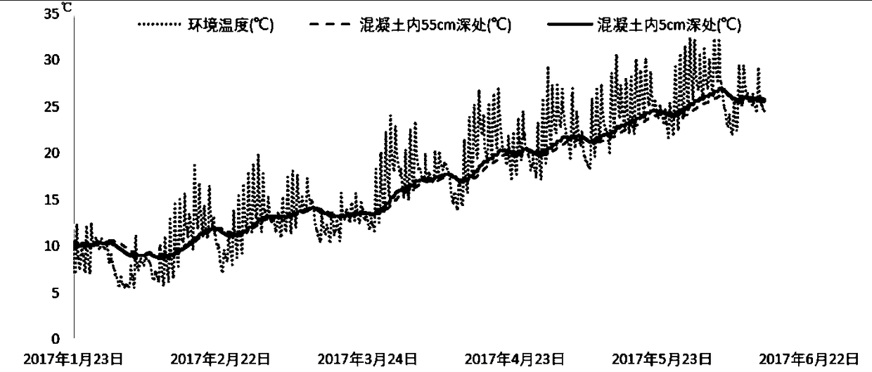
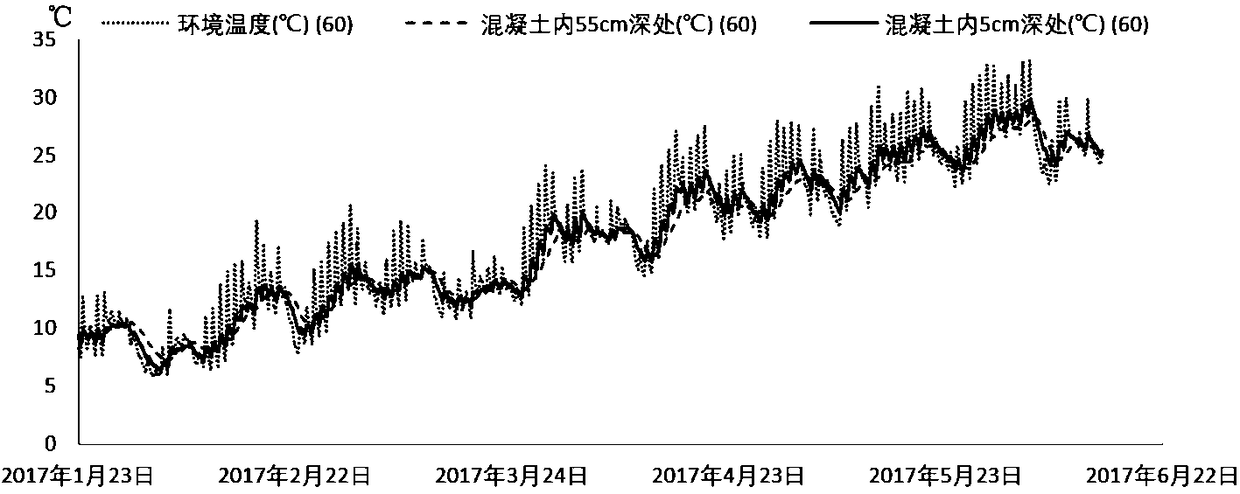

Image

  • Gridded temperature control system for concrete dam
  • Gridded temperature control system for concrete dam
  • Gridded temperature control system for concrete dam

Examples


Embodiment Construction

[0102] The present invention will be further described in detail below in conjunction with the accompanying drawings and specific embodiments.

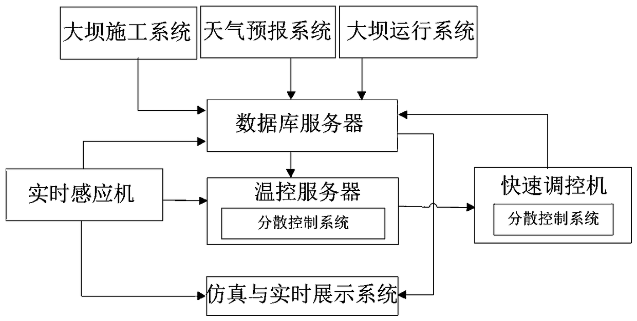
[0103] Such as image 3 As shown, the gridded dam temperature control system includes a real-time induction machine 2, a temperature control server, and a fast control machine 3 connected in sequence, and also includes a database server, a database server and a dam construction system, a weather forecast system, and a dam operation system connect.

[0104] Such as Figure 5 As shown, the fast control machine 3 includes 2 industrial computers 31, 2 temperature compensation sources 32, 3 PLC controllers, a variable topology pipe network 33 and a wireless base station 34, and the variable topology pipe network 33 includes gridded A plurality of six-way control units 331, a temperature compensation source 32, a PLC controller, and a wireless base station 34 are connected to the industrial computer 31 respectively, and the six-way contro...


PUM


Abstract

The invention discloses a gridded temperature control system for a concrete dam. The gridded temperature control system for the concrete dam comprises a real-time inductor, a temperature control server and a rapid regulation-control machine which are sequentially connected. The gridded temperature control system for the concrete dam further comprises a database server, wherein the rapid regulation-control machine comprises a plurality of industrial personal computers, a plurality of temperature compensation sources, a plurality of PLCs, a pipe network with a variable topology structure and a wireless base station, the pipe network with the variable topology structure comprises a plurality of gridded multi-pass control units, and the temperature compensation sources, the PLCs and the wireless base station are connected with the industrial personal computers separately; the database server is connected with the real-time inductor and the rapid regulation-control machine separately; and the pipe network with the variable topology structure is arranged in a dam body. According to the gridded temperature control system for the concrete dam, a temperature control pipeline for the dam isgridded, and a sensor group is arranged around grid nodes, so that the flexibility and pertinence of temperature regulation-control for the dam are improved; and adverse factors possibly occurring inthe temperature regulation-control for the dam are predicated in advance, and a traditional passive temperature regulation-control manner is changed into active temperature regulation-control, so thatthe uncertainty of the temperature regulation-control for the dam is reduced.

Description

technical field [0001] The invention belongs to the fields of water conservancy and hydropower project construction and concrete dam project operation temperature control, and in particular relates to a gridded concrete dam temperature control system. Background technique [0002] With the rapid development of my country's national economy, the development of hydropower in areas rich in water resources such as the central east and southwest has gradually become more perfect, and the development and planning of national water conservancy and hydropower projects have shifted to the northwest region. The advancement of technology has made it no longer a problem to build high concrete dams in Northwest China. However, due to the complex climate conditions in Northwest my country, cold and dry winters, and large temperature differences between day and night, the problem of "no dams and no cracks" in concrete dams has become more prominent. . Most of the existing temperature contr...

Claims


Application Information

Patent Timeline
IPC IPC(8): E02D15/02
CPCG05D23/20
Inventor 杜彬张秀崧田斌张子瑞乐阳谭琨杜钢张敏刘敏卢晓春童富果徐港
Owner 宜昌天宇科技有限公司
Learn More