Organic electroluminescent element

A luminescent, organic field technology, applied in the field of organic electroluminescent components

Inactive Publication Date: 2018-12-21
NIPPON STEEL CHEMICALL &MATERIAL CO LTD
View PDF30 Cites 0 Cited by
  • Summary
  • Abstract
  • Description
  • Claims
  • Application Information

AI Technical Summary

Problems solved by technology

Patent Document 8 discloses the use of a specific carborane compound as a delayed fluorescent light-emitting material, or the use of biscarbazole compounds as a delayed fluorescent light-emitting material and the use of a carborane compound as a host material in the light-emitting layer, but does not teach Mixing a carborane compound with a specific carbazole compound and using it as a host material for organic layers other than the light-emitting layer and light-emitting layers

Method used


Image

  • Organic electroluminescent element
  • Organic electroluminescent element
  • Organic electroluminescent element

Examples


Embodiment 1

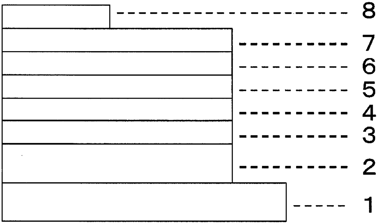
[0136]On a glass substrate on which an anode made of indium tin oxide (ITO) with a film thickness of 70 nm was formed, a vacuum deposition method was used to obtain a vacuum of 2.0×10 -5 Pa laminates each film. First, on ITO, copper phthalocyanine (CuPC) was formed to a thickness of 30 nm as a hole injection layer. Next, 4,4-bis[N-(1-naphthyl)-N-phenylamino]biphenyl (NPB) was formed as a hole transport layer with a thickness of 15 nm. Next, as the light-emitting layer, compound 1-2 as the first host, compound 2-1 as the second host, and iridium complex [bis(4,6-difluorobenzene] which is a blue phosphorescent material as the guest of the light-emitting layer base)-pyridine-N,C2']iridium picolinate(III)](FIrpic) was co-evaporated from different evaporation sources to form a light-emitting layer with a thickness of 30 nm. At this time, the vapor deposition rate ratio (wt ratio) of the first body, the second body, and FIrpic was 47:47:6. Next, Alq is formed with a thickness of ...

Embodiment 2~21

[0139] In Example 1, organic EL elements (Examples 2 to 7) were produced in the same manner as in Example 1, except that the compounds described in Table 1 were used as the first host of the light-emitting layer.

[0140] In addition, organic EL elements (Examples 8 to 21) were produced in the same manner as in Examples 1 to 7, except that Compounds 2-18 and 2-29 were used as the second host of the light-emitting layer.

[0141] When an external power source was connected to the obtained organic EL element and a DC voltage was applied, an emission spectrum with a maximum wavelength of 475 nm was observed from any organic EL element, and it was found that light emission from FIrpic was obtained. Table 1 shows the characteristics of the produced organic EL elements.

Embodiment 22

[0151] On a glass substrate on which an anode made of ITO with a film thickness of 150 nm was formed, a vacuum degree of 4.0×10 was carried out by a vacuum deposition method. -4 Pa laminates each film. First, CuPc was formed as a hole injection layer with a thickness of 20 nm on ITO, and then NPB was formed as a hole transport layer with a thickness of 20 nm. Next, as the light-emitting layer, compound 1-2 as the first host, compound 2-1 as the second host, and tris(2-phenylpyridine)iridium(III)(Ir(PPy) as the guest of the light-emitting layer 3 ) were co-evaporated from different evaporation sources, and formed with a thickness of 30 nm. At this time, the first body, the second body and Ir(PPy) 3 The evaporation rate ratio of 47:47:6. Next, bis(2-methyl-8-hydroxyquinoline)4-phenylphenolaluminum(III)(BAlq) was formed as a hole blocking layer with a thickness of 10 nm. Next, Alq was formed with a thickness of 40 nm 3 as an electron transport layer. Further, LiF was formed...


PUM


Abstract

The purpose of the present invention is to provide an organic EL element which exhibits high driving stability and high luminous efficiency at a low voltage. Provided is an organic electroluminescentelement in which an anode, organic layers and a cathode are laminated on a substrate, wherein a biscarbazole compound (i) represented by general formula (1) and a carborane compound (ii) having one ormore carborane rings and an aromatic group bonded to the carborane ring(s) are contained in at least one of the organic layers. Here, R and R' each denote a hydrogen atom, an aromatic hydrocarbon group, a heterocyclic group, an alkyl group, or the like, m is a number between 1 and 6, and X1 to X3 are each N, C-R' or C-.

Description

technical field [0001] The present invention relates to an organic electroluminescence element (hereinafter, referred to as an organic EL element), and more specifically, to an organic EL element having an organic layer containing a plurality of compounds. Background technique [0002] By applying a voltage to the organic EL element, holes are injected into the light-emitting layer from the anode, and electrons are injected into the light-emitting layer from the cathode, respectively. Furthermore, in the light-emitting layer, the injected holes and electrons recombine to generate excitons. At this time, according to the statistical law of electron spin, singlet excitons and triplet excitons are generated in a ratio of 1:3. It can be said that the internal quantum efficiency has a limit of 25% using a fluorescent light-emitting organic EL element that emits light based on singlet excitons. On the other hand, it is known that a phosphorescent light-emitting type organic EL e...

Claims


Application Information

Patent Timeline
Patent Type & Authority Applications(China)
IPC IPC(8): H01L51/50
CPCH10K85/322H10K85/654H10K85/6572H10K50/18H10K50/11H10K2101/10H10K2101/90H10K50/12H10K85/615H10K85/6574H10K85/6576H10K50/15H10K50/16H10K50/171H10K85/342H10K85/344H10K85/346H10K85/348H10K85/371
Inventor 小川淳也池永裕士上田季子多田匡志
Owner NIPPON STEEL CHEMICALL &MATERIAL CO LTD
Why Eureka
Try Eureka