Method for preparing hollow microneedle array
A microneedle array and hollow technology, which is applied in the field of micromachining, can solve the problems of complex preparation process, high cost and poor structure controllability of the hollow microneedle array, and achieves the effects of high cost, simple operation and uniform material.
- Summary
- Abstract
- Description
- Claims
- Application Information
AI Technical Summary
Problems solved by technology
Method used
Image

Examples
Embodiment 1~7
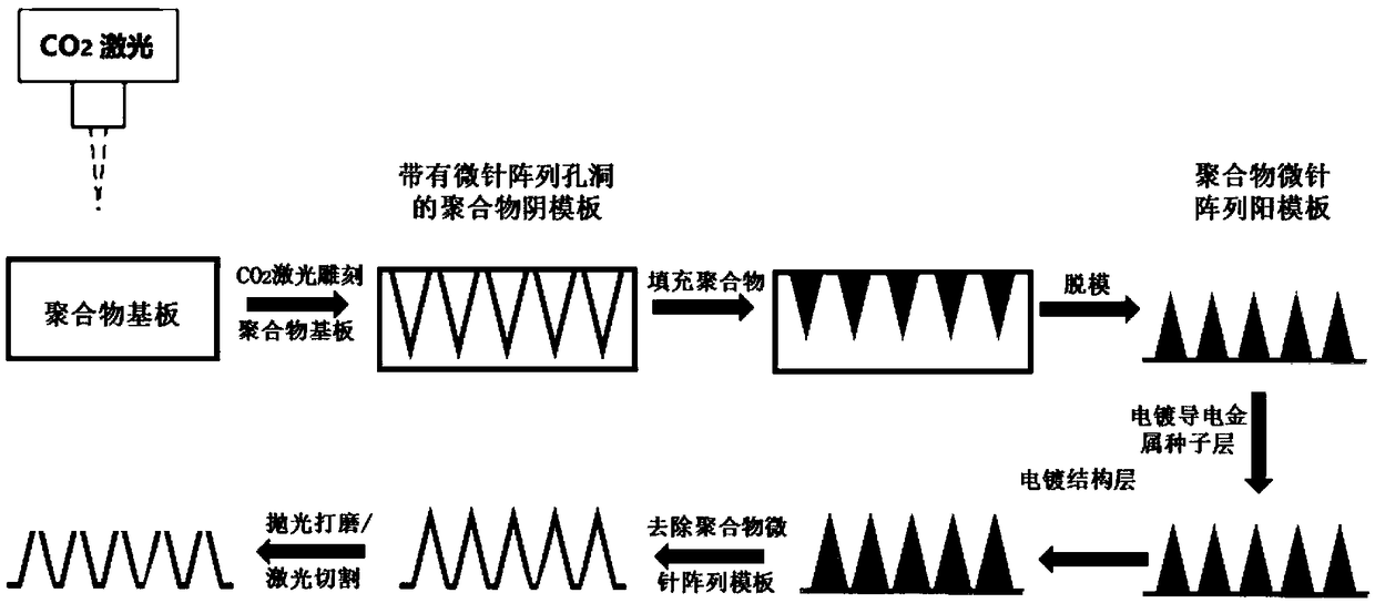
[0031] In summary, Embodiments 1 to 7 all include the following steps:
[0032] 1. Preparation of the PMMA microneedle array negative template: adjust the laser engraving machine processing parameters (as shown in Table 1), so that the laser etches microneedle holes of different sizes on the PMMA substrate;
[0033]2. Preparation of PDMS microneedle array positive template: Mix PDMS (Sylgard 184) and curing agent evenly at a mass ratio of 10:1, let stand for a period of time to remove the air bubbles in the mixture, and add the above-mentioned PMMA microneedle array positive template. Vacuum the surface of the template for several minutes to allow PDMS to enter and fill the holes to obtain a positive PDMS microneedle array template with the same size as the PMMA microneedle array negative template;
[0034] 3. Coating a layer of silver seed layer on the surface of PDMS microneedle array positive template by silver mirror reaction;
[0035] 4. Electroplating a metal nickel (Ni...
Embodiment 8~13
[0042] In summary, Embodiments 8 to 13 all include the following steps:
[0043] 1. Preparation of PDMS substrate: Mix PDMS (Sylgard 184) and curing agent evenly at a mass ratio of 10:1, let it stand for a while to remove the air bubbles in the mixture, and then heat it at 100°C for 1 hour to make it completely solidified. Obtain the PDMS substrate;
[0044] 2. Preparation of the negative template of the PDMS microneedle array: adjust the processing parameters of the laser engraving machine so that the laser power is 100W, the laser scanning speed is 10 mm / s, and the number of times is 1, so that the laser can etch on the PDMS substrate with a length of about 2000μm microneedle array negative template;
[0045] 3. Preparation of polymethyl methacrylate (PMMA) microneedle array positive template: place the PMMA plate on the surface of the above-mentioned PDMS microneedle array negative template engraved with holes, heat and vacuum, so that PMMA enters and fills the holes, Obt...
Embodiment 14
[0054] This embodiment comprises the following steps:
[0055] 1. Preparation of PDMS substrate: Mix PDMS (Sylgard 184) and curing agent evenly at a mass ratio of 10:1, let it stand for a while to remove the air bubbles in the mixture, and then heat it at 100°C for 1 hour to make it completely solidified. Obtain the PDMS substrate;
[0056] 2. Preparation of the negative template of the PDMS microneedle array: adjust the processing parameters of the laser engraving machine so that the laser power is 100W, the laser scanning speed is 10 mm / s, and the number of times is 1, so that the laser can etch on the PDMS substrate with a length of about 2000μm microneedle array negative template;
[0057] 3. Preparation of the positive template of the polypropylene microneedle array: place the polypropylene plate on the surface of the negative template of the PDMS microneedle array engraved with holes above, heat and vacuumize, so that the polypropylene enters and fills the holes, and th...
PUM
| Property | Measurement | Unit |
|---|---|---|
| Length | aaaaa | aaaaa |
| Thickness | aaaaa | aaaaa |
Abstract
Description
Claims
Application Information
 - Generate Ideas
- Intellectual Property
- Life Sciences
- Materials
- Tech Scout
- Unparalleled Data Quality
- Higher Quality Content
- 60% Fewer Hallucinations
Browse by: Latest US Patents, China's latest patents, Technical Efficacy Thesaurus, Application Domain, Technology Topic, Popular Technical Reports.
© 2025 PatSnap. All rights reserved.Legal|Privacy policy|Modern Slavery Act Transparency Statement|Sitemap|About US| Contact US: help@patsnap.com