A fiber optic sensing system based on fiber laser

A fiber optic sensing system and fiber laser technology, applied in the direction of lasers, laser components, phonon exciters, etc., can solve problems such as difficult to filter clean, variable frequency, unfavorable fiber optic sensors, etc., to achieve a wide range of applications, The phase detection error is small and the effect of improving the sensing accuracy

Inactive Publication Date: 2019-11-19
JILIN UNIV
View PDF5 Cites 0 Cited by
  • Summary
  • Abstract
  • Description
  • Claims
  • Application Information

AI Technical Summary

Problems solved by technology

However, on the one hand, the high-frequency component itself will affect the phase detection of the cosine wave (the position of the zero-crossing point changes); The electrical characteristics are equivalent to capacitance, and the voltage at both ends cannot jump, so the falling edge of the sawtooth wave cannot be infinitely short) and the elasticity of the optical fiber itself and many other factors, the frequency is variable, and it is difficult to filter out cleanly; and , when using a filter, in addition to affecting the amplitude-frequency characteristics of the output signal, it will also affect the phase-frequency characteristics of the signal at the same time, that is, the phase of the filter will be affected near the cut-off frequency, which is very important for relying on phase changes. It is very disadvantageous for fiber optic sensors that measure changes in stress

Method used


Image

  • A fiber optic sensing system based on fiber laser
  • A fiber optic sensing system based on fiber laser
  • A fiber optic sensing system based on fiber laser

Examples


Embodiment 1

[0028] Embodiment 1 Overall structure of the present invention

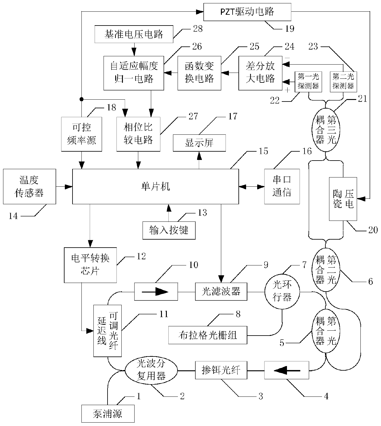
[0029] Such as figure 1 As shown, the overall structure of the present invention has, pumping source 1 (the LC962U type pumping source of OCLARO company, central wavelength 980nm, maximum single-mode output optical power is 750mW) is connected with the 980nm end of optical wavelength division multiplexer 2, light wave The 1550nm end of the division multiplexer 2 (980 / 1060nm single-mode fiber wavelength division multiplexer of COMCORE) and the adjustable delay line fiber 11 VDL-40-15-S9-1-FA type of Sichuan Yuxingguang Technology Co., Ltd. One end of the electric fiber delay line) is connected, the other end of the delay line adjustable line 11 is connected with the input end of the first optical isolator 10 (1550nm polarization-independent optical isolator), the control end of the delay line adjustable line 11 is connected to the level The output port of conversion chip 12 (MAX232) is connected, and level conve...

Embodiment 2

[0031] Embodiment 2 function transformation circuit

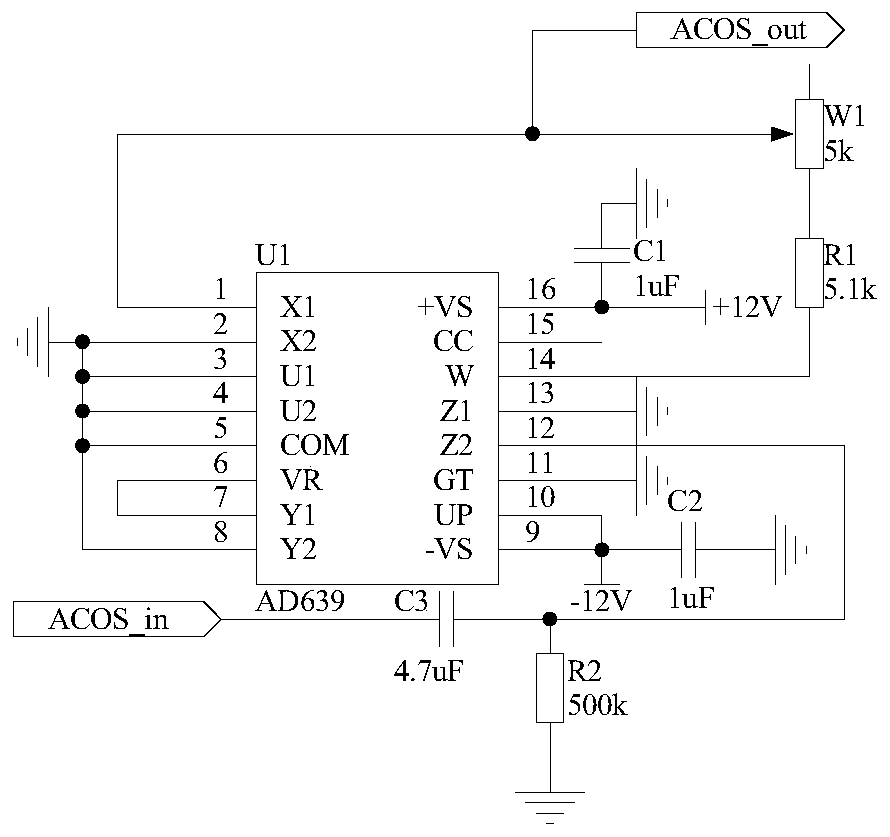
[0032] Such as figure 2 As shown, the structure of the function conversion circuit 25 used in the present invention is that one end of the capacitor C3 is connected to the pin 12 of the trigonometric function converter U1 and one end of the resistor R2, and the other end of the capacitor C3 is used as the input end of the function conversion circuit 25 , recorded as the port ACOS_in, connected to the output end of the differential amplifier circuit 24; the other end of the resistor R2 is grounded; the pins 2, 3, 4, 5, 8, 11, 13 of the trigonometric function converter U1 are grounded, and the pins 9, 10 is connected to one end of capacitor C2 and -12V power supply, and the other end of capacitor C2 is grounded; pin 6 of trigonometric function converter U1 is connected to pin 7, pin 16 is connected to +12V power supply and one end of capacitor C1, capacitor C1 The other end of the trigonometric function converter U1 is conn...

Embodiment 3

[0033] Embodiment 3 Adaptive Amplitude Normalization Circuit

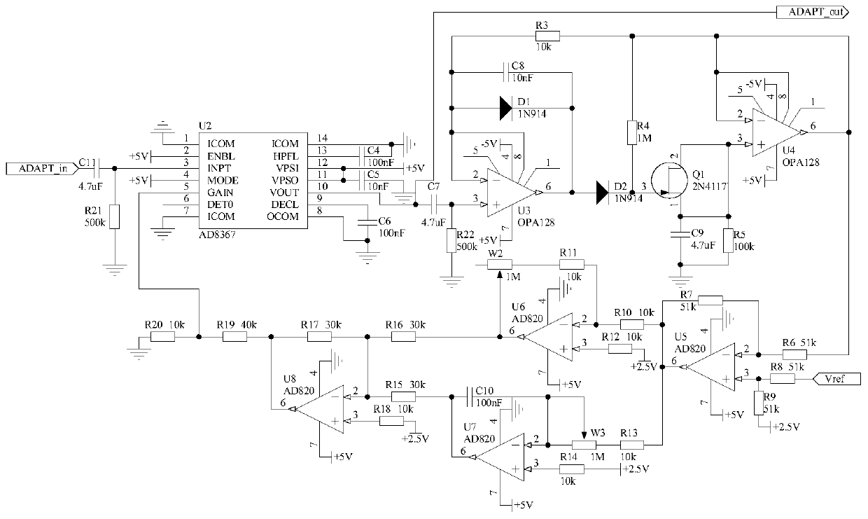
[0034] Because the amplitude of the signal output by the function conversion circuit 25 is small, and is affected by multiple parameters in the optical path and the circuit, the size is indefinite, so the present invention has designed an adaptive amplitude normalization circuit 26, which is used to convert the signal output by the function conversion circuit 25 The amplitude is normalized to the optimal size to further improve the accuracy of demodulation. The structure of the adaptive amplitude normalization circuit 26 is that one end of the capacitor C11 is connected with one end of the resistor R21 and the pin 3 of the chip U2, the other end of the resistor R21 is grounded, and the other end of the capacitor C11 is used as an adaptive amplitude normalization The input terminal of the circuit 26 is recorded as the port ADAPT_in, and is connected with the port ACOS_out of the function conversion circuit 25; the p...


PUM


Abstract

The invention relates to an optical fiber sensing system based on an optical fiber laser and belongs to the technical field of optical fiber sensors. Its main structures include a pump source (1), an optical wavelength division multiplexer (2), an erbium-doped optical fiber (3) and the like. The invention uses a sinusoidal signal as a modulation signal, does not generate high-frequency interference, and has the characteristics of more reliable operation, high sensing precision, wide application range and the like.

Description

technical field [0001] The invention belongs to the technical field of optical fiber sensors, in particular to an optical fiber sensing system based on optical fiber lasers. Background technique [0002] Fiber Bragg grating (FBG) is widely used in the field of sensing technology due to its advantages of anti-electromagnetic interference, chemical resistance, small transmission loss, small size and light weight, and easy mass production. Especially in micro-stress detection, temperature detection in harsh environments, etc., fiber optic sensors have unique advantages. On the one hand, very small changes in temperature or stress can be detected sensitively by fiber Bragg gratings, with high sensitivity. On the one hand, in harsh environments such as humidity and strong electromagnetic interference, the fiber Bragg grating is not easy to damage, the working performance is not affected, and the signal transmission is not disturbed. These advantages make Bragg fiber grating sens...

Claims


Application Information

Patent Timeline
Patent Type & Authority Patents(China)
IPC IPC(8): G01K11/32H01S3/067G01K11/3206
CPCH01S3/067G01K11/3206
Inventor 吴戈张栋
Owner JILIN UNIV
Why Eureka
Try Eureka