Method of improving detecting sensitivity of micro-fluidic chip by non-contact conducting method

A microfluidic chip, non-contact conductance technology, applied in material impedance and other directions, can solve the problems of limited sensitivity improvement, high cost, and complicated operation, and achieve the effects of high sensitivity, low cost, and simple operation.

Inactive Publication Date: 2019-01-11
ZHUJIANG HOSPITAL SOUTHERN MEDICAL UNIV
View PDF3 Cites 2 Cited by
  • Summary
  • Abstract
  • Description
  • Claims
  • Application Information

AI Technical Summary

Problems solved by technology

However, these methods have very limited improvement in sensitivity
Moreover, these methods are also accompanied by the problems of high cost and cumbersome operation.

Method used


Image

  • Method of improving detecting sensitivity of micro-fluidic chip by non-contact conducting method
  • Method of improving detecting sensitivity of micro-fluidic chip by non-contact conducting method
  • Method of improving detecting sensitivity of micro-fluidic chip by non-contact conducting method

Examples


Embodiment 1

[0037] Embodiment 1, the method is used for the concentration detection of medicine---galantamine

[0038] This embodiment provides a method for improving the detection sensitivity of the non-contact conductometric method of the microfluidic chip. Since the drug galantamine is an ionizable substance, the detection of galantamine is taken as an example to illustrate the method for improving the detection sensitivity of the non-contact conductivity method of the microfluidic chip.

[0039] The method for improving the detection sensitivity of the non-contact conductometric method of the microfluidic chip in this embodiment includes the following steps:

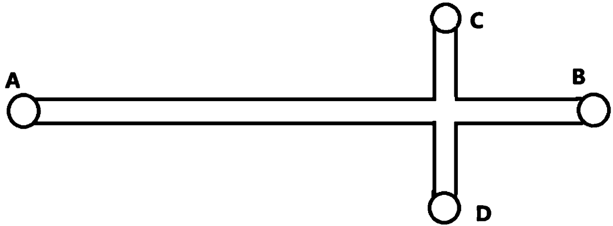
[0040] (1) Take the microfluidic chip (conventional cross-shaped PMMA microfluidic chip, see the structure figure 1 ), the microfluidic chip used in this embodiment is a reusable microfluidic chip.

[0041] (2) First use sodium hydroxide solution to activate the sampling channel and separation channel of the microfluidic chi...

Embodiment 2

[0048] This embodiment is a modification example of embodiment 1. Compared with embodiment 1, the main change is that in step (4), the buffer solution containing 40% ethanol by volume is added to the buffer storage tank.

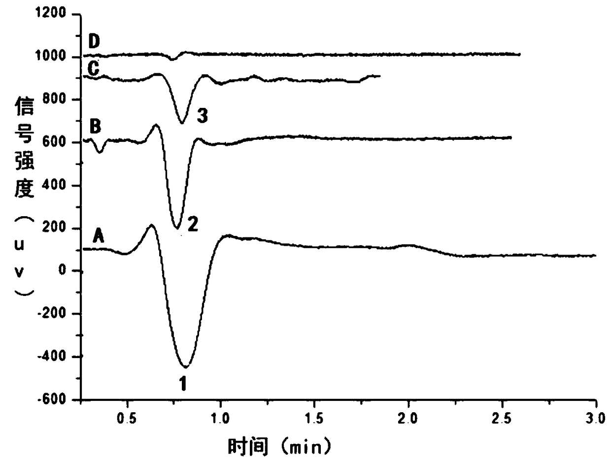
[0049] See the test results image 3 ,according to image 3 From the chromatogram shown in A, it can be seen that when the volume percentage of ethanol is 40%, the detection signal intensity is amplified.

Embodiment 3

[0051] This embodiment is a modification example of embodiment 1. Compared with embodiment 1, the main change is that in step (4), the buffer solution containing 30% ethanol by volume is added to the buffer storage tank.

[0052] See the test results image 3 ,according to image 3 From the chromatogram shown in B, it can be seen that when the volume percentage of ethanol is 30%, the detection signal intensity is amplified.


PUM


Abstract

The invention provides a method of improving detecting sensitivity of a micro-fluidic chip by a non-contact conducting method. The method comprises the following steps: taking the micro-fluidic chip and adding a buffer solution, wherein a sample pond, a sample waste liquor pond, a buffer solution storage pond, a buffer solution waste liquor pond, a feeding channel and a separating channel of the micro-fluidic chip are filled with the buffer solution; absorbing the buffer solution in the sample pond and the buffer solution storage pond; adding a to-be-tested sample solution prepared by the buffer solution into the sample pond and adding the buffer solution containing ethanol into the buffer solution storage pond, wherein the volume content of ethanol is greater than 10%; inserting an electrode, feeding the sample by taking the sample pond as an anode and the sample waste liquor pond as a cathode, and separating the sample by taking the buffer solution storage pond as an anode and the buffer solution waste liquor pond as a cathode after sample feeding; and repeating sample feeding and separating for at least one time after sample feeding and separating. By adopting the detection method, the detection limit can be lower to 10 pg / ml. The method is very high in sensitivity, and can achieve micro-fluidic chip well. In addition, the method is simple to operate, low in cost and high inpracticality.

Description

technical field [0001] The invention relates to the field of microfluidic chip detection, in particular to a method for improving the detection sensitivity of the microfluidic chip non-contact conductance method. Background technique [0002] Miniaturization and integration are important directions for the development of modern analytical instruments. Microfluidic chips have the characteristics of small size, less consumption of samples and reagents, fast analysis speed, simple sample processing, and high separation efficiency. Microfluidic chips can be highly integrated, and the entire analysis process of sample injection, reaction, filtration, separation, and detection can be realized on a chip of a few square centimeters. [0003] The detectors used in microfluidic chips mainly include: ultraviolet-visible light absorption detectors, fluorescence detectors, laser-induced fluorescence detectors, chemiluminescence detectors, conductivity detectors, amperometric detectors, ...

Claims


Application Information

Patent Timeline
Patent Type & Authority Applications(China)
IPC IPC(8): G01N27/02
CPCG01N27/02
Inventor 杨秀娟李智磊陈缵光王勇
Owner ZHUJIANG HOSPITAL SOUTHERN MEDICAL UNIV
Why Eureka
Try Eureka