
Dielectric integrated suspension line WLAN dual-passband low noise amplifier

A low-noise amplifier and medium integration technology, applied in the direction of low-noise amplifiers, amplifiers, radio frequency amplifiers, etc., can solve problems such as complex circuit structures, achieve the effects of reducing circuit components, realizing filtering, and reducing circuit area

Active Publication Date: 2019-01-11
成都智芯测控科技有限公司
View PDF5 Cites 1 Cited by
  • Summary
  • Abstract
  • Description
  • Claims
  • Application Information

AI Technical Summary

Problems solved by technology

In order to realize impedance transformation in existing low noise amplifiers, an impedance transformation circuit needs to be installed, and its circuit structure is complex

Method used


Image

  • Dielectric integrated suspension line WLAN dual-passband low noise amplifier
  • Dielectric integrated suspension line WLAN dual-passband low noise amplifier
  • Dielectric integrated suspension line WLAN dual-passband low noise amplifier

Examples


Embodiment 1

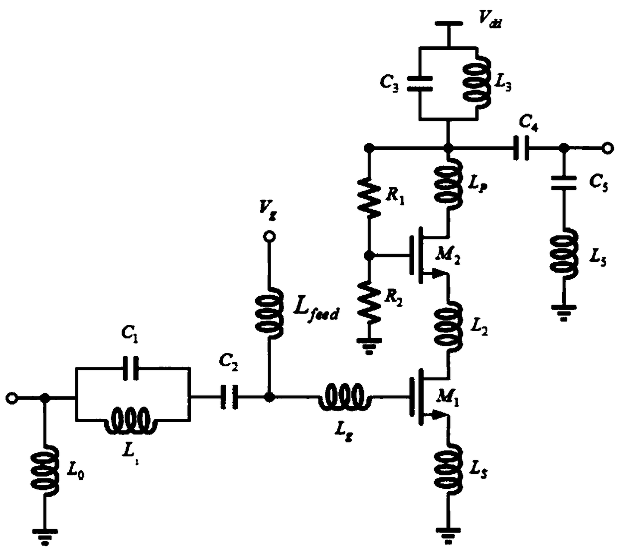
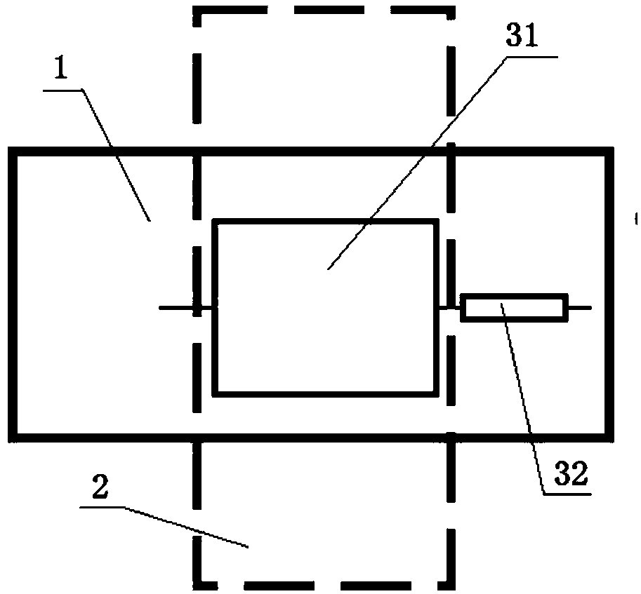
[0026] A medium-integrated suspension line WLAN dual-passband low-noise amplifier, including a low-noise amplifier, the low-noise amplifier is composed of discrete components, and the discrete components are connected by a transmission line structure. The transmission line structure includes a dielectric layer 1, which is respectively arranged on the dielectric layer The transmission line on both sides and the ground layer 2, the transmission line includes a first transmission line 31 and a second transmission line 32 connected in sequence, the line width of the first transmission line is 5.8mm to 6.2mm, and the line length is 4.2mm to 4.5mm; The line width of the second transmission line is 0.8 mm to 1.0 mm, and the line length is 3.2 mm to 3.5 mm. In this transmission line scheme, the characteristic impedance of the first transmission line is between 48-52 ohms, the characteristic impedance of the second transmission line is between 133-145 ohms, and the imaginary part of the...

Embodiment 2

[0037] On the basis of any structure given in Embodiment 2, this embodiment continues to optimize, that is, the low noise amplifier is integrated on the medium-integrated suspension line platform.

[0038] The dielectric integrated suspension line platform includes five layers of double-sided printed circuit boards laminated from top to bottom, including ten metal layers from M1 to M10, and an intermediate dielectric is filled between the two metal layers of each circuit board. The middle of the second-layer circuit board and the fourth-layer circuit board has a hollow structure, so as to ensure that the third-layer circuit board and the first-layer circuit board and the fifth-layer circuit board form an air cavity structure; the medium integrated suspension line is large Part of the electromagnetic field is distributed in the air cavity, which greatly reduces the dielectric loss of the electromagnetic field. The metal layers M2 and M9 serve as signal grounds for the suspensio...


PUM


Abstract

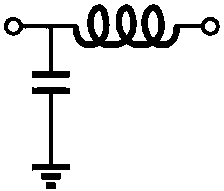
The present invention discloses a dielectric integrated suspension line WLAN dual-passband low noise amplifier. The medium integrated suspension line WLAN dual-passband low noise amplifier comprises alow noise amplifier, a transmission line structure is connected between discrete devices of the low noise amplifier, the transmission line structure comprises a dielectric layer and a transmission line and a grounding layer which are respectively arranged at two sides of the dielectric layer, the transmission line comprises a first transmission line and a second transmission line which are connected in order, the line width of the first transmission line is 5.8-6.2mm, and the line length of the first transmission line is 4.2-4.5mm; and the line width of the second transmission line is 0.8-1.0mm, and the line length of the second transmission line is 3.2-3.5mm. The first transmission line forms a low-impedance line which is equivalent to a capacitor structure having one end earthed; and the second transmission line form a high-impedance line which is equivalent to an inductance structure connected in series in the circuit. The transmission line structure is employed to achieve a filtering effect and achieve an impedance conversion effect.

Description

technical field [0001] The invention relates to the field of low-noise amplifiers, in particular to a medium-integrated suspension line WLAN dual-pass-band low-noise amplifier. Background technique [0002] WLAN has become the mainstream communication method for mobile communication devices today. The traditional WLAN widely adopts the 2.4GHz frequency band based on the IEEE802.11b / g standard, and the bandwidth is only 83MHz. The limited bandwidth and rate can no longer meet today's data communication needs, so the International Institute of Electrical and Electronics Engineers IEEE launched the 802.11a standard to extend the carrier frequency to the 5GHz frequency band. In order to reduce cost, save space, and reduce circuit complexity, it is urgent to integrate multiple communication standards and communication frequency bands in one design platform. System operators worldwide are turning to dual-band equipment in order to meet the increasing number of subscribers. At p...

Claims


Application Information

Patent Timeline
Patent Type & Authority Applications(China)
IPC IPC(8): H03F1/56H03F3/193
CPCH03F1/565H03F3/193H03F2200/294H03F2200/451Y02D30/70
Inventor 牟首先柯正敏马凯学孟凡易
Owner 成都智芯测控科技有限公司
Learn More