Biomass-energy sludge fuel rod for enhancing energy recovery
A technology of biomass energy and energy recovery, applied in the direction of biofuel, waste fuel, fuel, etc., to achieve full combustion, improved combustion performance, and high calorific value
- Summary
- Abstract
- Description
- Claims
- Application Information
AI Technical Summary
Problems solved by technology
Method used
Image
Examples
Embodiment 1
[0030] Embodiment 1, the first kind of biomass sludge fuel rod shape design
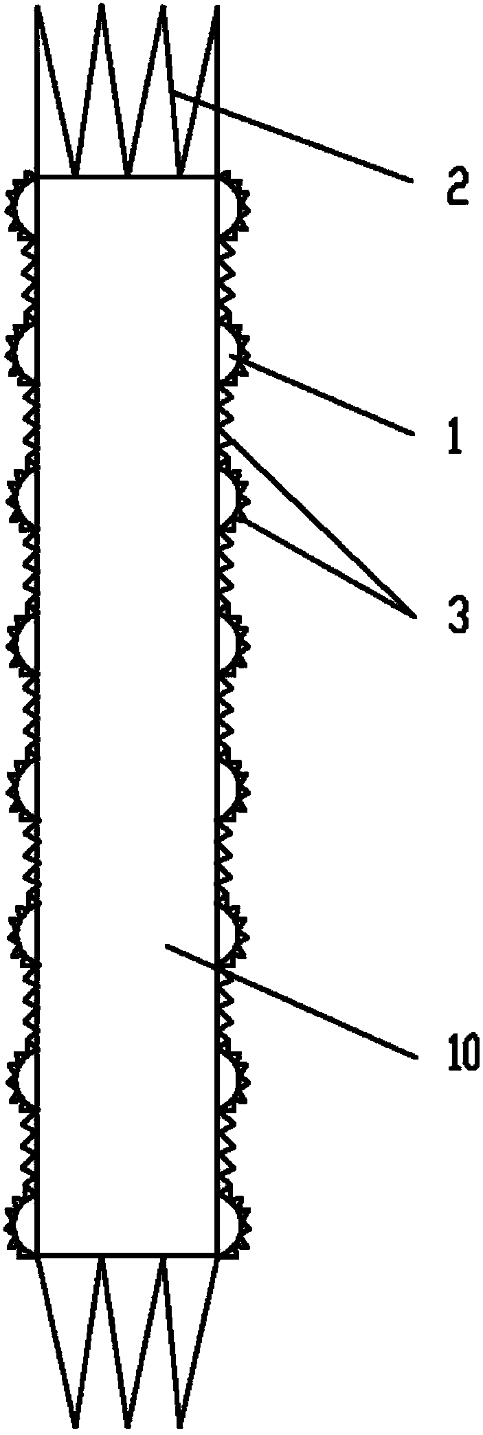
[0031] Referring to the accompanying drawings, the structure of the first specific embodiment of the present invention includes a rod-shaped body 10 constructed from industrial sludge. The overall shape of this rod-shaped body 10 is a cylinder. Many block-shaped protrusions 1 are distributed on the surface of the body, and the block-shaped protrusions 1 are arranged in the shape of a hemisphere. Further, the end surface of the rod-shaped body 10 is set as a tooth-shaped protrusion 2, and finally, the outer surface of the rod-shaped body 10 is coated with a thin layer of colloid, which completely covers the cylindrical surface of the rod-shaped body 10 , and cover the block-shaped protrusions 1 and the serrations 3 on the surface of the cylinder.
Embodiment 2
[0032] Embodiment 2, the second kind of biomass sludge fuel rod shape design
[0033] Referring to the accompanying drawings, the second embodiment of the present invention differs from the first embodiment in that: the outer surface of the rod-shaped body 10 is coated with a thin layer of colloid, and this thin layer of colloid is completely covered on the rod-shaped body. 10 on the surface of the cylinder and the surface of the end, and cover the block-shaped protrusions 1 on the surface of the cylinder, the serrations 3 and the tooth-shaped protrusions 2 on the surface of the end.
Embodiment 3
[0034] Embodiment 3, the preparation method of the biomass sludge that fuel rod is used
[0035] The preparation method of the biomass sludge used in embodiment 1, 2 may further comprise the steps:
[0036] A. The environmental protection department, tannery and fuel rod factory jointly build a wastewater pipeline to transport the tannery wastewater to the sewage treatment pool of the fuel rod factory;
[0037] B. Take the crushed and dried organic waste from agriculture, forestry and animal husbandry, add it to the sewage treatment tank in step A, and stir evenly to form an organic solid-liquid mixture. The organic waste from agriculture, forestry and animal husbandry is made of crop straw, tree branches, and slag leftovers , dry and pulverize before use, the amount of organic waste from forestry and animal husbandry to be added is based on the overall moisture content of the material after feeding is between 40-50% w / w;
[0038]C. Add the activated fermentation bacteria gro...
PUM
| Property | Measurement | Unit |
|---|---|---|
| diameter | aaaaa | aaaaa |
Abstract
Description
Claims
Application Information
 - R&D
- Intellectual Property
- Life Sciences
- Materials
- Tech Scout
- Unparalleled Data Quality
- Higher Quality Content
- 60% Fewer Hallucinations
Browse by: Latest US Patents, China's latest patents, Technical Efficacy Thesaurus, Application Domain, Technology Topic, Popular Technical Reports.
© 2025 PatSnap. All rights reserved.Legal|Privacy policy|Modern Slavery Act Transparency Statement|Sitemap|About US| Contact US: help@patsnap.com

