
Rotation illumination-based surface wave imaging system

An imaging system and surface wave technology, applied in measuring devices, material analysis through optical means, instruments, etc., can solve the problems of single working environment, low signal-to-noise ratio, high cost, etc., and achieve diverse working environments and high time resolution , Realize the effect of real-time observation

Pending Publication Date: 2019-01-18
UNIV OF SCI & TECH OF CHINA
View PDF7 Cites 6 Cited by
  • Summary
  • Abstract
  • Description
  • Claims
  • Application Information

AI Technical Summary

Problems solved by technology

[0007] The purpose of the present invention is to overcome the shortcomings of traditional surface wave imaging microscopes such as low signal-to-noise ratio, poor temporal and spatial resolution, single working environment and high cost, and propose a surface wave imaging system based on rotating illumination

Method used


Image

  • Rotation illumination-based surface wave imaging system
  • Rotation illumination-based surface wave imaging system
  • Rotation illumination-based surface wave imaging system

Examples


Embodiment Construction

[0032] The present invention will be further described in detail below in conjunction with the accompanying drawings and specific embodiments.

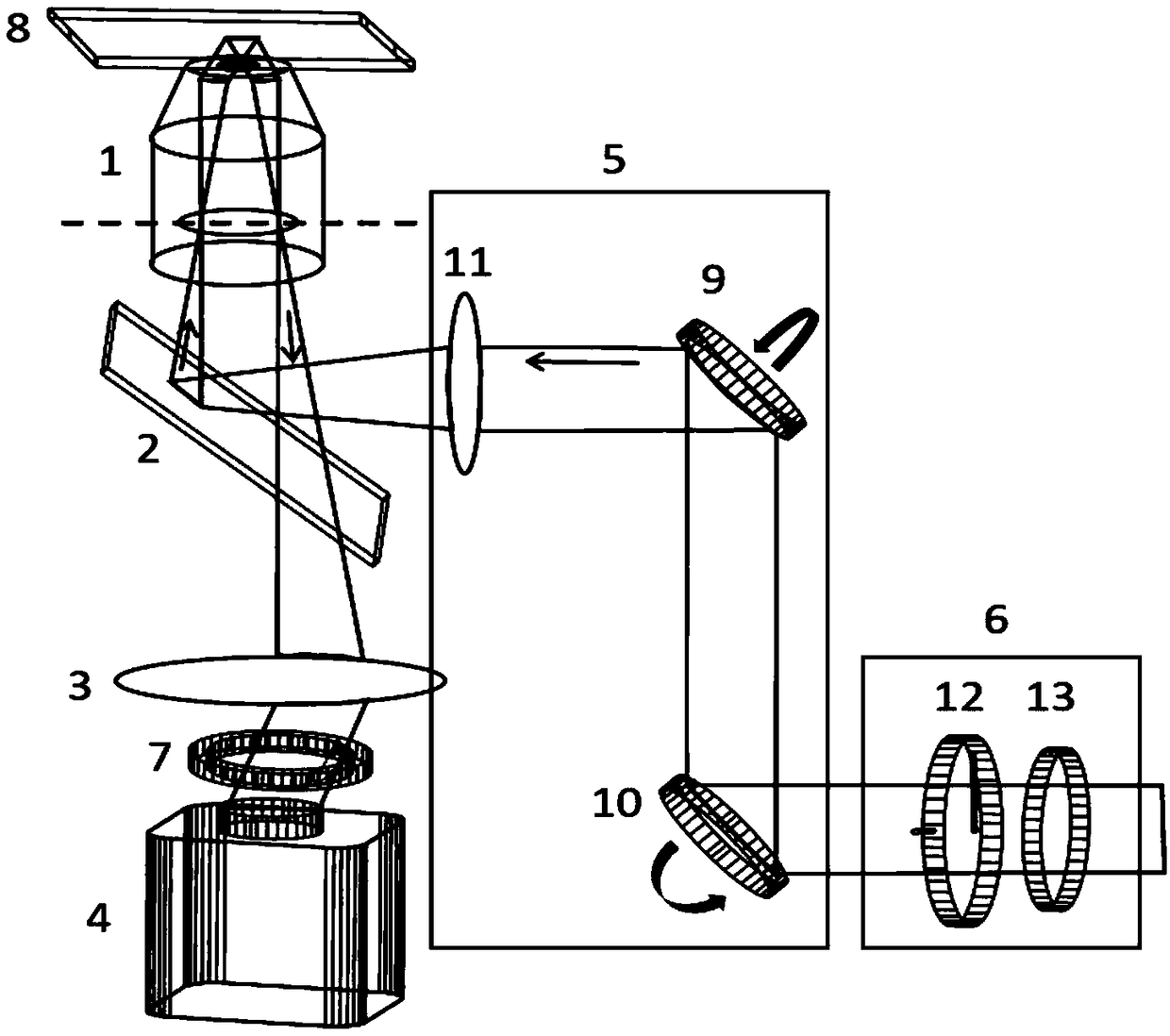
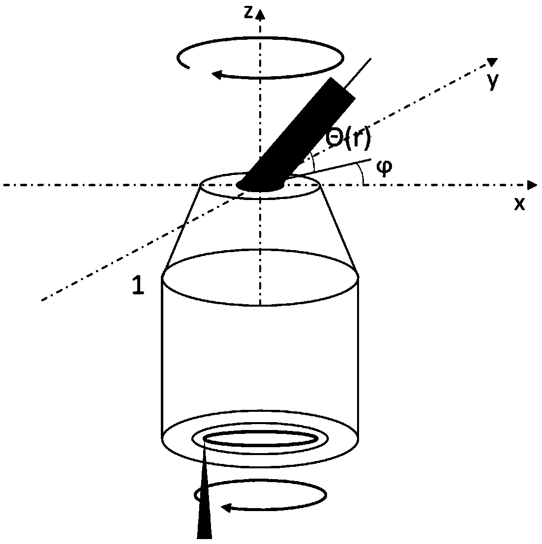
[0033] The present invention is a surface wave imaging system based on rotating illumination, comprising an oil-immersed microscope objective lens, a beam splitter, an imaging tube lens, an image plane detector, a scanning galvanometer system on the rear focal plane of the objective lens, a polarization modulation device, a polarization separation device and Surface wave imaging substrate; wherein, the polarization modulation device modulates a broadband linearly polarized light beam with any polarization direction, and can work in the visible wavelength range of 400nm-700nm, which is used as the excitation light of the surface wave.

[0034] Among them, the oil immersion objective with a numerical aperture of 1.49 provides the large wave vector required to excite surface waves.

[0035] Among them, the scanning galvanometer system on...


PUM

PropertyMeasurementUnit
diameteraaaaaaaaaa
diameteraaaaaaaaaa
thicknessaaaaaaaaaa

Abstract

The invention discloses a rotation illumination-based surface wave imaging system. The rotation illumination-based surface wave imaging system comprises an oil-immersed microscope objective (1), a beam splitter (2), an imaging pipe lens (3), an image surface detector (4), an objective back focal plane scanning galvanometer (5), a polarization modulation device (6), a polarization separation device(7) and a surface wave imaging substrate (8), wherein a surface wave such as surface plasmon resonance or Marc Bloch surface wave can be effectively constrained on a surface of a substrate and is very sensitive to environmental change, the surface wave is simulated by laser to act with a surface sample by the objective, the signal-to-noise ratio is improved by the polarization separation device,and trailing brought by imaging after the surface wave acts on the sample is eliminated by a galvanometer scanning system. The device initially uses rotation illumination to improve the signal-to-noise ratio and the resolution of micro imaging of the surface wave, and a multi-layer dielectric film photonic band gap structure is initially used for performing micro imaging of the surface wave.

Description

technical field [0001] The invention relates to the field of high-sensitivity surface optical microscopic imaging, in particular to the field of surface wave imaging based on rotating illumination. Background technique [0002] Microscopic technology is the most direct means for people to understand the microscopic world. Optical microscopy technology presents the image of the microscopic world directly in front of our eyes. It is the most intuitive and commonly used microscopic technology among all microscopic technologies. Surface wave microscopy uses surface waves, mainly the surface plasmon resonance at the interface between metal and air, as an illumination source, and utilizes its strong locality in surface propagation and is very sensitive to disturbances at the interface to achieve High-sensitivity imaging of samples adjacent to metallic coating surfaces. The above-mentioned main microscopy techniques have great limitations in practical application, and the existing...

Claims


Application Information

Patent Timeline
Patent Type & Authority Applications(China)
IPC IPC(8): G01N21/552
CPCG01N21/554
Inventor 蒯雁张斗国
Owner UNIV OF SCI & TECH OF CHINA
Learn More