A circuit topology structure suitable for bidirectional near-field power transmission

A technology of circuit topology and power transmission, applied in circuit devices, high-efficiency power electronic conversion, output power conversion devices, etc., can solve problems such as increasing system costs, changes in coil electrical parameters, and large frequency bandwidth resources, and reduce manufacturing costs. Difficulty and cost, high performance and high reliability, and the effect of reducing reactive power loss

Pending Publication Date: 2019-01-18
ARMY ENG UNIV OF PLA
View PDF17 Cites 26 Cited by
  • Summary
  • Abstract
  • Description
  • Claims
  • Application Information

AI Technical Summary

Problems solved by technology

At present, the resonant frequency of the existing resonance compensation network is determined by the inductance or capacitance, coil self-inductance or mutual inductance in the compensation network. When the relative position between the coils changes, the coil self-inductance, mutual inductance and coupling coefficient between the coils will change accordingly. In addition, under different working temperature environments, the magnetic permeability of the ferrite in the coil structure will also change, which will lead to changes in the electrical parameters of the coil
In addition, the inductance error and capacitance error caused by mass production cannot be avoided
Therefore, in actual work, the resonant frequency will change to a certain extent. If the switching frequency deviates too much from the resonant frequency, it will cause serious problems such as hard switching of the high-frequency inverter and excessive reactive power loss; if the switching frequency follows If the resonant frequency changes, the system will occupy a large frequency bandwidth resource under different working conditions. On the one hand, the relevant domestic and international standards have limited the operating frequency range; on the other hand, the wider operating frequency range will make the system EMC design is more complex and increases system cost

Method used


Image

  • A circuit topology structure suitable for bidirectional near-field power transmission
  • A circuit topology structure suitable for bidirectional near-field power transmission
  • A circuit topology structure suitable for bidirectional near-field power transmission

Examples


Embodiment 1

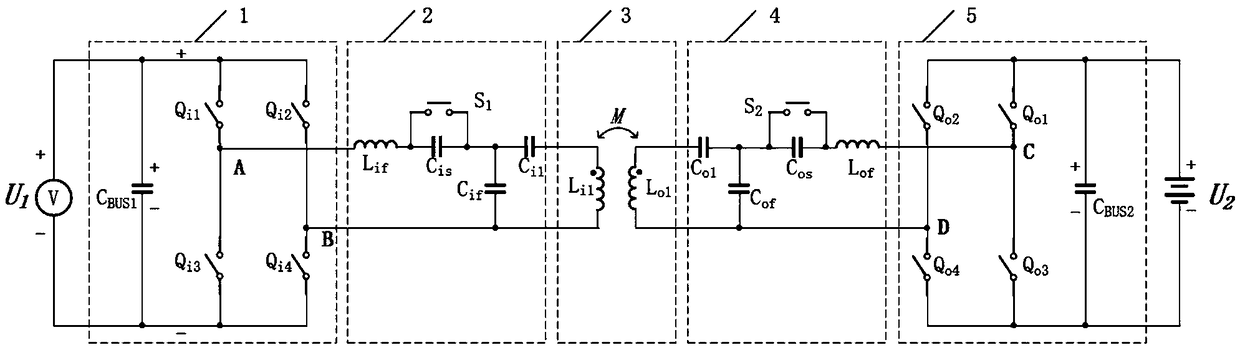
[0040] A circuit topology suitable for bidirectional near-field power transfer systems such as figure 1 shown, including input DC power U 1 , full bridge inverter circuit 1, primary side resonance dynamic compensation network 2, primary side coil 3L i1 , secondary coil 3L o1 , secondary resonance dynamic compensation network 4, full-bridge synchronous rectification circuit 5 and load battery U 2 , the specific topological structure of the full-bridge inverter circuit 1, the primary-side resonant dynamic compensation network 2 and the secondary-side resonant dynamic compensation network 4, and the full-bridge synchronous rectification circuit 5 is about the primary-side coil 3L i1 , secondary coil 3L o1 symmetry;

[0041] The full-bridge inverter circuit 1 includes a first bus capacitor C BUS1 , four switching tubes Q i1 -Q i4 , the first bus capacitance C BUS1 The positive pole of the input DC power supply U 1 positive connection of the first bus capacitor C BUS1 The...


PUM


Abstract

The invention discloses a circuit topology structure suitable for bidirectional near-field power transmission, which comprises a full-bridge inverter, a primary-side resonant dynamic compensation network, a primary-side coil, a secondary-side coil, a secondary-side resonant dynamic compensation network, a full-bridge synchronous rectification and a load. The invention can realize bidirectional near-field transmission of electric energy, and at different coil coupling coefficients, at different load size and due to temperature, under the condition of system parameter change caused by manufacturing error of device, by adjusting the PWM duty cycle of the capacitor switching switch, the equivalent capacitance of the capacitor switching switch can change continuously to compensate the resonantnetwork dynamically, so as to realize the soft switching of the full-bridge inverter, to minimize the reactive power in the energy transmission of the system, and to maximize the energy transmission efficiency of the system. In addition, due to the symmetry of the circuit structure, it can realize the bidirectional transmission of near-field electric energy, that is, the bidirectional energy flowbetween the power grid and the load, which improves the utilization rate of the system in the smart grid.

Description

technical field [0001] The invention relates to power electronic topological circuit technology, in particular to a circuit topological structure suitable for two-way near-field electric energy transmission. Background technique [0002] The near-field power transmission is to convert the high-frequency circuit into an alternating electromagnetic field through the primary coil, and the high-frequency induced current generated in the secondary coil is converted into a DC output by a rectifier circuit. In recent years, this technology has been widely used in wireless charging products for smartphones. In addition, this technology also has broad application prospects in the fields of household robots, industrial robots, and electric vehicles. [0003] In order to improve the energy transmission distance and efficiency, a resonance compensation network can be added to the primary coil and the secondary coil respectively to form a magnetic resonance. At present, the resonant fre...

Claims


Application Information

Patent Timeline
Patent Type & Authority Applications(China)
IPC IPC(8): H02M3/335H02J50/12H02J5/00
CPCH02J5/005H02J50/12H02M3/33523H02M3/33584H02M3/33592Y02B70/10
Inventor 李建科
Owner ARMY ENG UNIV OF PLA
Why Eureka
Try Eureka