
Method and device for detecting super capacitor in pitch system

A super capacitor and pitch system technology, applied in capacitance measurement, measurement device, measurement of electrical variables, etc., can solve the problems of power grid fluctuations, affecting power generation, labor costs and time costs, and achieve accurate calculation accuracy and reduce detection costs. , to achieve the effect of online detection

Active Publication Date: 2019-02-01
BEIJING GOLDWIND SCI & CREATION WINDPOWER EQUIP CO LTD
View PDF6 Cites 9 Cited by
  • Summary
  • Abstract
  • Description
  • Claims
  • Application Information

AI Technical Summary

Problems solved by technology

[0006] 1) In the shutdown mode of the wind turbine, cut off the output of the charger, consume the energy of the supercapacitor through energy-consuming equipment such as a motor, and then turn on the charger to charge the supercapacitor, and test the capacitance of the supercapacitor during the charging process; Because the output of the charger needs to be cut off first, the method must be tested in the shutdown mode, and online detection cannot be realized (detection when the wind turbine is running); in addition, this method is not conducive to the realization of automatic testing, because automatic testing can only use timing measurement When the automatic measurement time is up, all wind turbines will be disconnected from the grid for capacity detection, which will affect the power generation on the one hand, and on the other hand, may cause fluctuations in the grid due to the batch disconnection of wind turbines; while the manual test mode Next, because the charger needs to be cut off, for the sake of safety, the three blades are generally tested one by one, so the whole test takes a long time, generally takes 15 minutes. For the entire wind farm, the loss of power generation cannot be underestimated;
[0007] 2) During the operation of the wind turbine, directly cut off the output of the charger for a period of time, wait for the supercapacitor to drop to a certain value, and then turn on the charger to charge the supercapacitor; the disadvantage of this method is: since the purpose of detecting the supercapacitor is In order to monitor the performance of the supercapacitor, cutting off the charger without knowing the performance of the supercapacitor has certain hidden dangers to the safety of the wind turbine;
[0008] 3) Use a discharge device to manually detect the discharge of the supercapacitor. This method requires shutdown and testers to board the wind turbine for testing, and its labor and time costs are high.

Method used

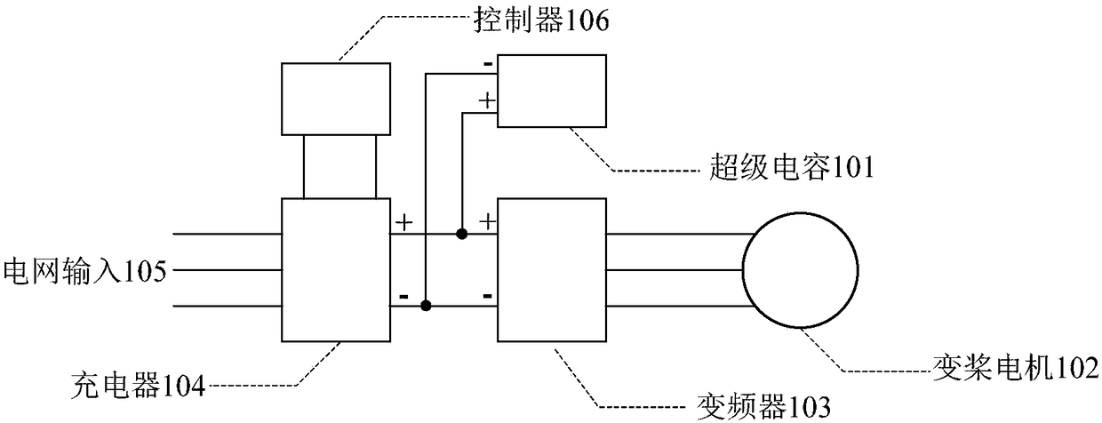
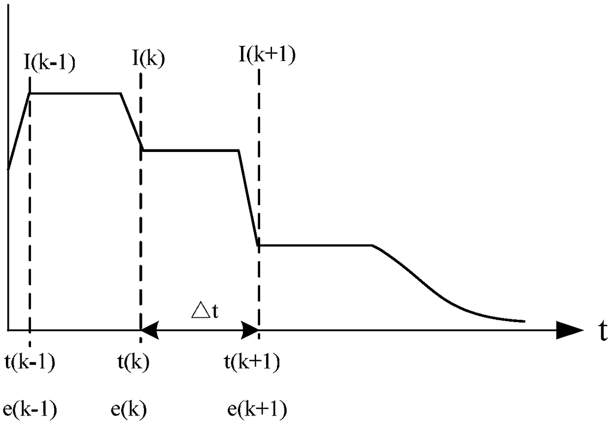
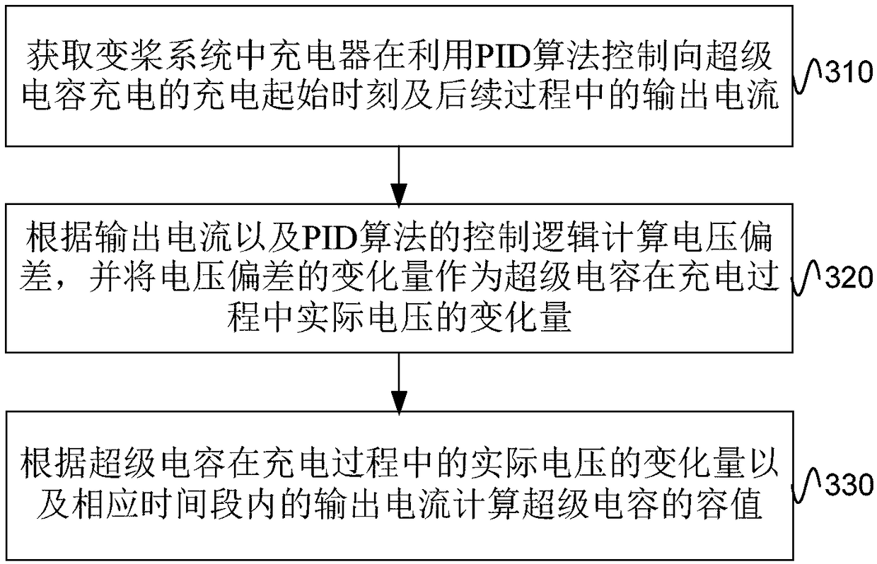

Image

  • Method and device for detecting super capacitor in pitch system
  • Method and device for detecting super capacitor in pitch system
  • Method and device for detecting super capacitor in pitch system

Examples


Embodiment 2

[0043] Figure 4 Flowchart of the detection method for the supercapacitor in the pitch system provided by the embodiment of the present invention Figure II , the method can be viewed as image 3 A specific implementation of the method shown. Such as Figure 4 As shown, the method includes the following steps:

[0044] S410. Obtain each output current value of the charger during the process of using the PID algorithm to control the charging of the supercapacitor, and the duration of each output current value. This step can be regarded as the detailed content of step S310.

[0045] Specifically, combined with figure 2 The parameter changes of the supercapacitor in the charging process shown in , when obtaining the current output by the PID algorithm for charging the supercapacitor, the output current value can be counted to obtain each output current value and its corresponding duration . E.g figure 2 Among them, the duration corresponding to the output current value ...

Embodiment 3

[0069] Figure 5 It is a schematic structural diagram of a detection device for a supercapacitor in a pitch system provided by an embodiment of the present invention, and the detection device is used to perform the method steps shown in the above-mentioned embodiments. Such as Figure 5 As shown, the detection device includes:

[0070] The current acquisition module 510 is used to acquire the output current of the charger in the pitch control system at the initial moment of charging to the supercapacitor by using the PID algorithm and the subsequent process. The control input used by the PID algorithm is the supercapacitor. The voltage deviation between the constant voltage value and the actual voltage value, the given voltage value is a fixed value, and the voltage deviation at the beginning of charging is 0;

[0071] The voltage calculation module 520 is used to calculate the voltage deviation according to the control logic of the output current and the PID algorithm, and ...


PUM


Abstract

The embodiment of the invention provides a method and a device for detecting a super capacitor in a pitch system. The method comprises the following steps of: acquiring a charging start time in the pitch system in which a charger uses a PID algorithm to control the charging of the super capacitor, and an output current in a subsequent process, wherein the control input quantity adopted by the PIDalgorithm is the voltage deviation between a given voltage value and an actual voltage value of the super capacitor, the given voltage value is a fixed value, and the voltage deviation at the chargingstart time is 0; calculating the voltage deviation according to the output current and the control logic of the PID algorithm, and taking the change amount of the voltage deviation as the change amount of the actual voltage of the super capacitor in the charging process; and calculating the capacitance value of the super capacitor according to the change amount of the actual voltage of the supercapacitor in the charging process and the output current in the corresponding time period. According to the scheme provided by the invention, the capacitance value of the super capacitor in the pitchsystem of the wind turbine can be detected quickly, conveniently and accurately, the detection process does not need to be stopped, and the online detection can be realized.

Description

technical field [0001] The invention relates to the technical field of wind power, in particular to a method and device for detecting a supercapacitor in a pitch control system. Background technique [0002] When the wind turbine (referred to as "wind turbine") is in normal operation, when the wind speed exceeds the rated wind speed of the unit, in order to control the power output, the pitch control system keeps the speed of the wind rotor constant by controlling the pitch angle of the blades. When the wind turbine fails, the pitch control system will perform an emergency propeller retraction function to realize pneumatic braking and ensure the safety of the unit. In the case of normal power supply from the grid, the pitch control system relies on the grid to work; when the grid fails (such as grid power failure or low voltage ride through), the pitch control system needs to have a backup power supply to power the pitch operation, in order to prevent In the event of a majo...

Claims


Application Information

Patent Timeline
Patent Type & Authority Applications(China)
IPC IPC(8): G01R27/26G05B11/42
CPCG01R27/2605G05B11/42
Inventor 马磊李庆江
Owner BEIJING GOLDWIND SCI & CREATION WINDPOWER EQUIP CO LTD
Learn More