A device and process for ultra-low emission of flue gas in non-electric field

A technology in the field of flue gas, which is applied in the equipment and process field of multi-pollutant synergistic ultra-low emission of flue gas, can solve the problems of high environmental protection cost, increased environmental protection cost of enterprises, and inability to improve flue gas pollution, etc., to achieve stable and reliable operation, The effect of increasing operating costs

Active Publication Date: 2021-06-01
ZHEJIANG ZHENENG CATALYST TECH CO LTD
View PDF7 Cites 0 Cited by
  • Summary
  • Abstract
  • Description
  • Claims
  • Application Information

AI Technical Summary

Problems solved by technology

[0003] Existing technologies are difficult to achieve ultra-low emission control in the non-electric field
Although the treatment technologies for dust and sulfur oxides are mature, they often require the construction of special treatment equipment, which will lead to high environmental protection costs; even with the existing integrated technology, there are still flue gas pollutants that do not match the non-electric field Governance, inability to perfect the exhausted smoke pollution and other issues
[0004] For NOx, the existing low-temperature denitrification technology has poor stability, and the denitrification efficiency of SNCR technology is low, and the denitrification effect is difficult to guarantee
For VOCs gas, there has not been a well-recognized technology in China
As for the malodorous gases such as ammonia in the flue gas in the non-electric field, environmental protection enterprises have not yet attracted enough attention
If a separate removal device is installed for each of the above pollutants, it will greatly increase the environmental protection cost of the enterprise

Method used


Image

  • A device and process for ultra-low emission of flue gas in non-electric field

Examples


Embodiment Construction

[0026] Below in conjunction with accompanying drawing, the present invention is described in detail.

[0027] In order to make the object, technical solution and advantages of the present invention clearer, the present invention will be further described in detail below in conjunction with the accompanying drawings and embodiments. It should be understood that the specific embodiments described here are only used to explain the present invention, not to limit the present invention.

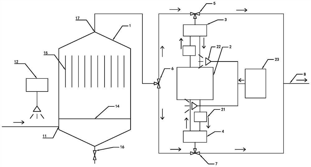
[0028] Such as figure 1 Shown: an ultra-low emission equipment for flue gas in the non-electric field, including a main tower 1 with a built-in deflector 14, a dust filter 15, a front RCO / RTO device 3, a rear RCO / RTO device 4 and an SCR catalyst In the SCR device 2, the outer wall surface of the bottom of the main tower 1 is provided with a flue gas inlet 11, and the top is provided with a flue gas outlet 17. Connected to the front RCO / RTO device 3 and the rear RCO / RTO device 4, the front RCO / RT...


PUM


Abstract

The invention discloses an ultra-low emission device for flue gas in the non-electric field, which includes a built-in guide plate, a main tower for filtering and dust removal parts, a front RCO / RTO device, a rear RCO / RTO device, and an SCR device equipped with an SCR catalyst. The outer wall of the bottom of the main tower is provided with a flue gas inlet, and the top is equipped with a flue gas outlet. A desulfurizer injection device is installed outside the flue gas inlet. The flue gas outlet is connected to the front RCO / RTO device and the rear RCO / RTO device through the inlet three-way valve. The front RCO / RTO device and the rear RCO / RTO device are heat storage reactors and are connected to the SCR device through one inlet pipeline and one outlet pipeline. The inlet pipeline is equipped with a reducing agent spray device, and the outlet pipeline is equipped with a SCO with built-in SCO catalyst. The reactor, the front RCO / RTO device and the rear RCO / RTO device are respectively connected to the net flue gas outlet. It can remove dust, desulfurize oxides, denitrify, deVOCs gas, and process malodorous gases such as ammonia, etc. It integrates multiple flue gas treatment functions and is suitable for collaborative processing devices and processes in non-electric fields.

Description

technical field [0001] The invention relates to the technical field of air pollution control, in particular to a device and process for synergistic ultra-low emission of flue gas multi-pollutants that can be applied to non-electric fields such as cement plants, biomass power plants, and steel plants. Background technique [0002] The complex and changeable flue gas working conditions are the main difficulties in the treatment of flue gas pollutants in the non-electric field. With the basic completion of ultra-low emissions of coal-fired units, ultra-low emissions in non-electric fields have been carried out in key areas such as iron and steel, and will inevitably be extended to cement, glass, biomass power plants, waste incineration and other fields in the future. Compared with coal-fired flue gas, flue gas in non-electric fields has a lower temperature and complex composition. In addition to sulfur oxides, nitrogen oxides (NOx), and dust, part of the flue gas also contains ...

Claims


Application Information

Patent Timeline
Patent Type & Authority Patents(China)
IPC IPC(8): B01D53/86B01D53/82B01D53/50B01D53/72B01D53/56B01D46/00F23G7/07F23J15/00
CPCB01D46/00B01D53/508B01D53/82B01D53/8625B01D53/8668B01D2251/206B01D2257/90B01D2258/0283F23G7/07F23J15/00
Inventor 刘长东尹顺利金震楠胡晨晖薛东武赵会民
Owner ZHEJIANG ZHENENG CATALYST TECH CO LTD
Why Eureka
Try Eureka