Novel projector light source structure with small size
A projector and small-volume technology, applied in the field of projection light sources, can solve the problems of large occupied volume, many lens components, complex optical path, etc., and achieve the effect of small occupied volume, few lens components and high output luminous flux
- Summary
- Abstract
- Description
- Claims
- Application Information
AI Technical Summary
Problems solved by technology
Method used
Image
Examples
Embodiment 1
[0044] This embodiment provides a new light source structure of a small volume projector, which has a simple optical path, uses few parts, occupies a small volume, and has low manufacturing cost.
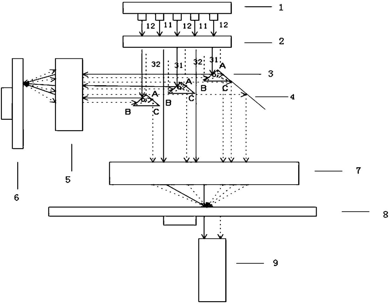
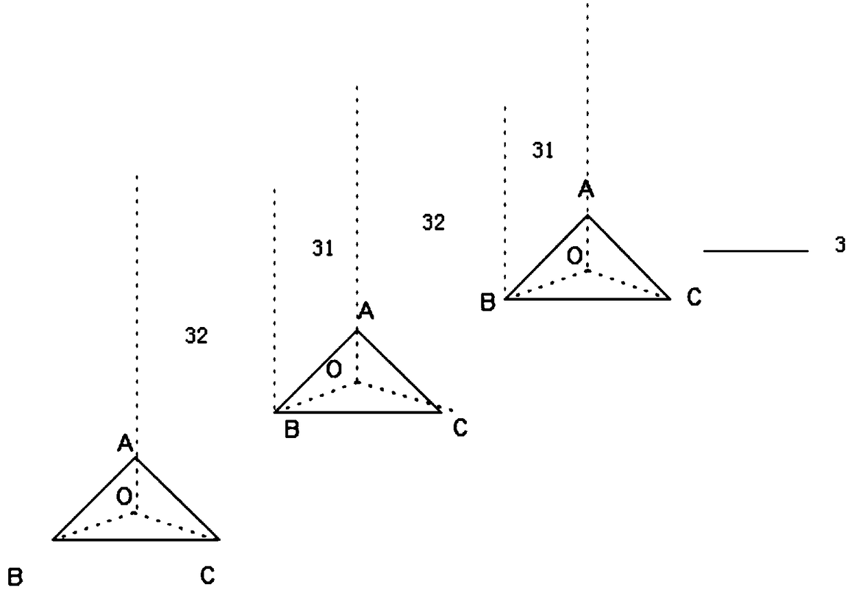
[0045] refer to Figure 2 to Figure 4 , specifically, the light source structure of the new small-volume projector includes a light source 1, a fluorescent wheel 6, a light splitting assembly 3 and a reflection assembly 4; the light splitting assembly 3 is arranged obliquely relative to the light source 1; Comprising a transmission area 31 and a reflection area 32; the laser light includes a transmission area laser 11 and a reflection area laser 12, the transmission area laser 11 passes through the transmission area 31, and the reflection area laser 12 is reflected to the fluorescent wheel 6 through the reflection area 32; the fluorescent wheel 6 is close to One side of the light-splitting component 3 is provided with a phosphor coating layer; the laser light 12 in the reflection ar...
Embodiment 2
[0058] refer to Figure 5 and Figure 6 , this embodiment is similar to Embodiment 1, the difference is that: the light splitting assembly 3 is arranged at intervals with dichroic mirrors 43, the reflection area 32 is a dichroic mirror 43, the coating is required to reflect blue laser light and transmit fluorescence, and the transmission area 31 is the gap where the dichroic mirror 43 is arranged. During specific implementation, the dichroic mirror 43 can be fixed through the slots of the upper cover and the lower cover of the structure.
[0059] In addition, in this embodiment, the light splitting component 3 can also adopt such as Figure 5 For the spacer coated glass, the reflective area 32 is required to be coated to reflect the blue laser light while transmitting the excited fluorescence, and the transmission area 31 is coated with an anti-reflection film or not coated to transmit the blue laser light and the fluorescent light. The spacer coating can be vertical strips...
Embodiment 3
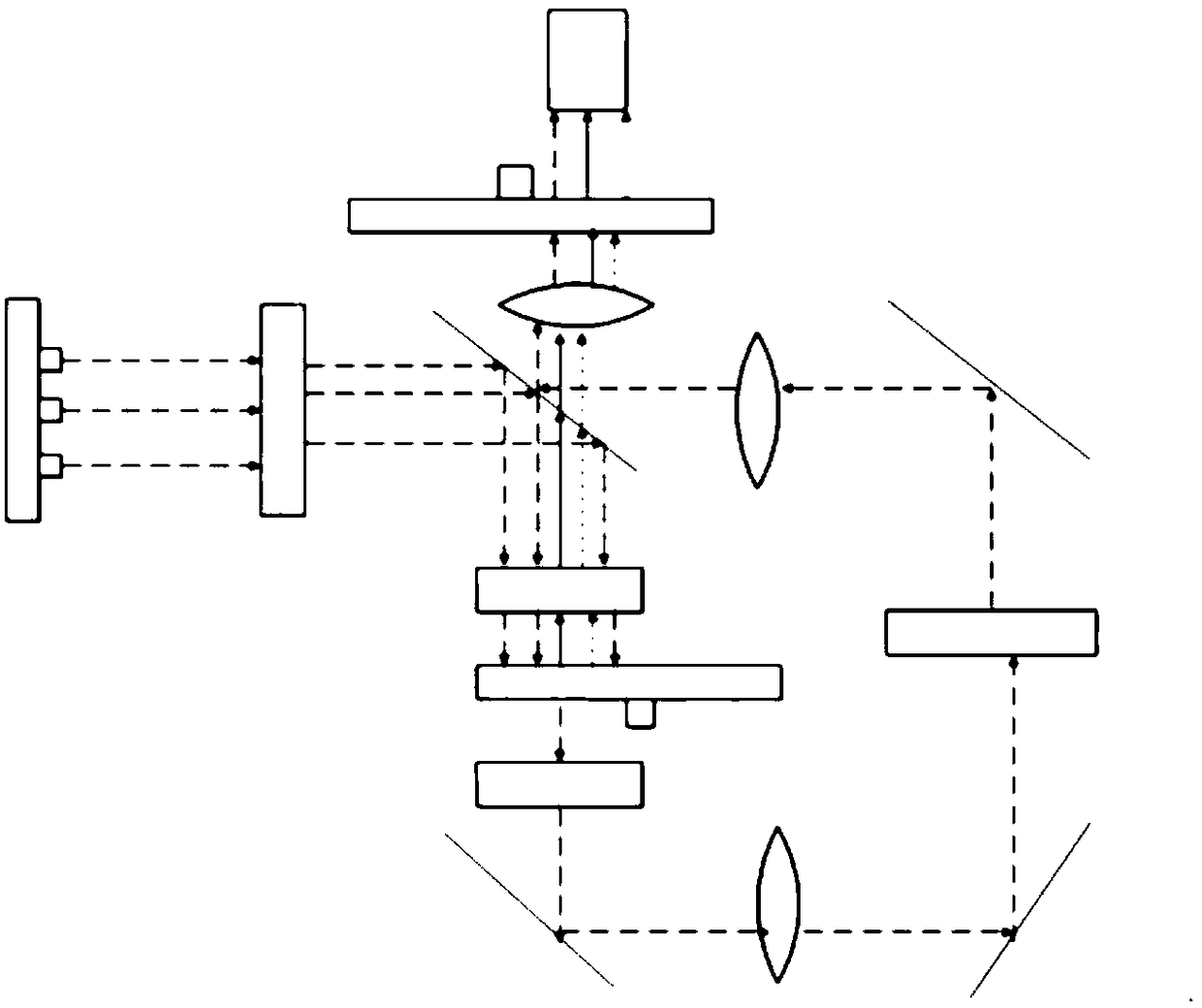
[0061] refer to Figure 7 The difference between this embodiment and Embodiment 2 is that the position of the reflective component 4 in the above Embodiment 2 is changed to reflect the transmitted laser light 11 in the transmission region so as to be consistent with the transmission direction of the excited fluorescence. The blue laser light generated by the light source 1 is reflected by the reflection area 32 of the spectroscopic assembly 3 to the fluorescent wheel 6 to excite the fluorescence, and at the same time transmits the wavelength bands other than the blue laser light. The transmission area 31 is opposite to the transmission area laser 11 and the The excited fluorescence is transmitted, and the fluorescence is combined with the laser light 11 in the transmission area and the light transmitted through the spectroscopic component 3 to be transmitted in the same direction. After passing through the focusing and shaping lens group, it enters the light rod 9 through the c...
PUM
 Abstract
Description
Claims
Application Information
 - R&D
- Intellectual Property
- Life Sciences
- Materials
- Tech Scout
- Unparalleled Data Quality
- Higher Quality Content
- 60% Fewer Hallucinations
Browse by: Latest US Patents, China's latest patents, Technical Efficacy Thesaurus, Application Domain, Technology Topic, Popular Technical Reports.
© 2025 PatSnap. All rights reserved.Legal|Privacy policy|Modern Slavery Act Transparency Statement|Sitemap|About US| Contact US: help@patsnap.com


