Waste heat recovery process and device

A kind of waste heat recovery equipment and waste heat recovery technology, applied in waste heat recovery process and its equipment, waste heat recovery process field, can solve the problems of unsatisfactory, environmental pollution, waste water reuse without replacement heat, etc.

Inactive Publication Date: 2019-03-01
山东圣普特节能环保科技有限公司
View PDF0 Cites 1 Cited by
  • Summary
  • Abstract
  • Description
  • Claims
  • Application Information

AI Technical Summary

Problems solved by technology

[0002] In the fields of chemical industry, pulping and papermaking, food fermentation, and biomedicine, exhaust gas emissions will cause energy waste and environmental pollution. Under the pressure of energy saving and environmental protection, waste heat recovery has become an industry development trend, and the sources of exhaust gas are intermittent and disorderly. , the current situation of unstable production, etc. is not conducive to recycling and full utilization. At present, the existing technology mainly adopts the washing tower washing process, through the direct heat exchange between the vapor phase and the liquid phase in the tower, and reverse washing to recover the waste heat of the exhaust gas. Although certain effects have been achieved, but The disposal of non-condensable waste gas and the full absorption and utilization of latent heat have not achieved satisfactory results
[0003] Due to the current situation of intermittent, disordered and unstable generation of waste gas, scrubbers are used to absorb the waste heat of waste gas, and stable replacement heat and sewage cannot be obtained for reuse. The treatment of non-condensable waste gas is mainly carried out in the form of high-altitude disorderly discharge. The exhaust gas has not been completely disposed of; the harmful substances contained in the high-pollutant exhaust gas are absorbed and dissolved in the hot sewage, and there is a secondary release of exhaust gas during reuse and the accumulation of pollutants in the process; due to the unstable discharge flow of exhaust gas, The latent heat absorption and replacement of waste gas; it is impossible to fully absorb and fully utilize the heat source

Method used


Image

  • Waste heat recovery process and device

Examples


Embodiment 1

[0026] Embodiment 1 A waste heat recovery process

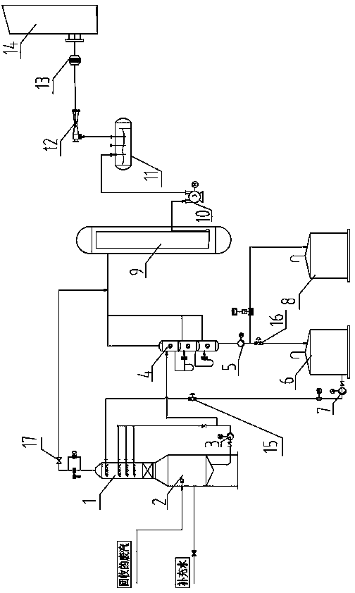
[0027] Such as figure 1 As shown, the present invention provides a waste heat recovery process, which is described by taking the case of pulping and papermaking cooking waste gas treatment as an example: when the system is started, clean water is injected into the heat storage tower 2 as a circulating fluid, and the cooking waste gas enters the heat storage tower 2 through the collection pipe. In the steam chamber at the upper part of the heat storage tower 2, the waste gas is initially depressurized and separated from the vapor and liquid. After separation, the waste gas enters through the built-in gas distributor of the absorption tower 1. (Circulating liquid or flash low-temperature water) is in a highly dispersed state, forming a full coverage of liquid in the tower. The lower main components are the gas distributor and the packing area. The gas distributor can make the gas entering the distributor under extremely high ki...

Embodiment 2

[0031] Embodiment 2 A kind of waste heat recovery equipment

[0032] Such as figure 1As shown, the present invention provides a waste heat recovery device, including an absorption tower 1, a heat storage tower 2, a circulation pump 3, a multi-stage flash tank 4, a return pump 5, a return tank 6, a liquid distribution pump 7, a sewage tank 8, Evaporation and concentration equipment 9, vacuum pump 10, odor collector 11, injector 12, flame arrester 13, burner 14.

[0033] The top of the heat storage tower 2 is connected to the absorption tower 1, and one side of the heat storage tower 2 is provided with a supplementary water port and a waste gas inlet;

[0034] The absorption tower 1 is provided with a two-layer nozzle pipe liquid distributor, and the two-layer nozzle pipe liquid distributor includes a lower nozzle pipe liquid distributor located in the middle of the absorption tower 1 and an upper nozzle pipe liquid distributor located at the upper part of the absorption tower ...


PUM


Abstract

The invention discloses a waste heat recovery process. The waste heat recovery process can fully recover exhaust emission heat energy and burn non-condensable gas, heat exchange circulation high-concentration sewage id discharged into a collecting tank and then into a sewage treatment system for treatment, and exhaust emission heat energy is recovered through two-stage heat absorption and accumulation. The invention also provides a waste heat recovery device. The waste heat recovery heat fully absorbs and utilizes exhaust waste heat and meanwhile achieves harmless treatment on the non-condensable gas to achieve zero-pollution emission. The waste heat recovery device is simple in operation, safe in working and free from pollution, and can meet demands on scale production, save cost and achieve high in economic benefits.

Description

technical field [0001] The invention relates to a waste heat recovery process, in particular to a waste heat recovery process and equipment thereof, and belongs to the technical field of waste gas heat recovery and reuse for energy-saving and environment-friendly production. Background technique [0002] In the fields of chemical industry, pulping and papermaking, food fermentation, and biomedicine, exhaust gas emissions will cause energy waste and environmental pollution. Under the pressure of energy saving and environmental protection, waste heat recovery has become an industry development trend, and the sources of exhaust gas are intermittent and disorderly. , the current situation of unstable production, etc. is not conducive to recycling and full utilization. At present, the existing technology mainly adopts the washing tower washing process, through the direct heat exchange between the vapor phase and the liquid phase in the tower, and reverse washing to recover the was...

Claims


Application Information

Patent Timeline
Patent Type & Authority Applications(China)
IPC IPC(8): B01D53/14B01D53/18F23G7/06F28D20/00F28D21/00
CPCB01D53/1412B01D53/1425B01D53/18B01D53/185F23G7/06F28D20/00F28D21/0003Y02E60/14
Inventor 武金龙
Owner 山东圣普特节能环保科技有限公司
Why Eureka
Try Eureka