
In-tube liquid drop preparing chip device

An internal droplet and chip technology, applied in the field of biochemical microfluidics, can solve problems such as complexity, difficulty in miniaturization of devices, increase in complexity of chip devices, etc., and achieve the effect of expanding the scope of application

Pending Publication Date: 2019-03-01
XI AN JIAOTONG UNIV
View PDF3 Cites 8 Cited by
  • Summary
  • Abstract
  • Description
  • Claims
  • Application Information

AI Technical Summary

Problems solved by technology

However, the droplets prepared in this method are often easy to gather near the droplet preparation unit, which affects the stable preparation of subsequent droplets. In the literature Macromolecular Chemistry & Physics, volume 218, 2017, p. 1600472, " High-Throughput StepEmulsification for the Production of Functional Materials Using a Glass Microfluidic Device" describes a high-throughput step emulsification chip device for glass substrates. By controlling the flow and flushing of the continuous phase reagents, the droplets are driven from the droplet preparation unit to solve the problem of The problem of the aggregation of droplets in the droplet preparation unit, but this increases the complexity of the chip device. After the droplets are prepared, they still need to be transferred to the reaction tube for subsequent reactions
The Chinese patent (publication number CN105413772B) provides a single / multi-component droplet preparation device based on an integrated microchannel, including a discrete phase input system and a droplet generation system, but the droplet preparation device described in this patent requires many The connection of individual components makes it difficult to miniaturize the device. The droplet preparation unit is composed of a discrete phase outlet joint composed of a microchannel plastic film and a splint and a backing plate, forming a series of integrated microchannels arranged in parallel and with the outlet downward. The droplet size Limited by its structure, it is difficult to reduce, and it is only suitable for the preparation of droplets whose discrete phase density is greater than that of the continuous phase
[0004] Therefore, the droplet preparation method of conventional step emulsification still has shortcomings in terms of device miniaturization and integration, and complex fluidic device and chip design are required to achieve large-scale preparation of small droplets.

Method used


Image

  • In-tube liquid drop preparing chip device
  • In-tube liquid drop preparing chip device
  • In-tube liquid drop preparing chip device

Examples


Embodiment 1

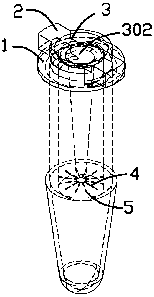
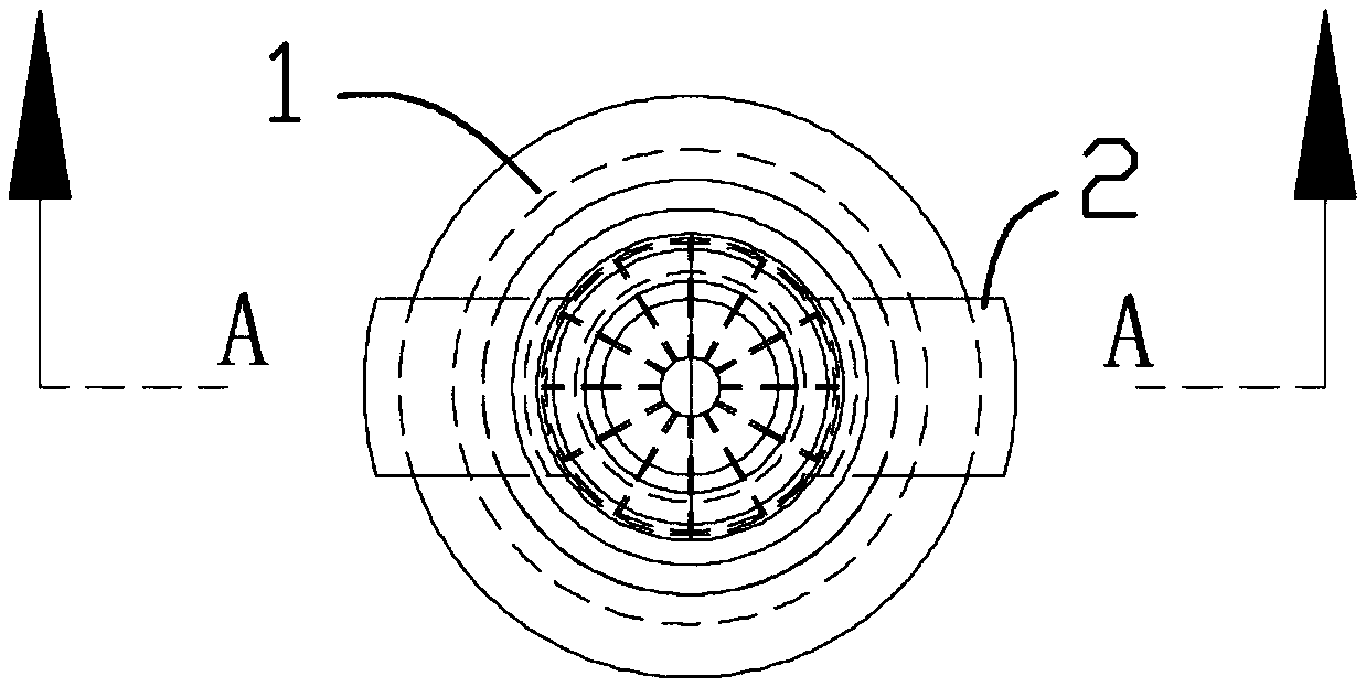
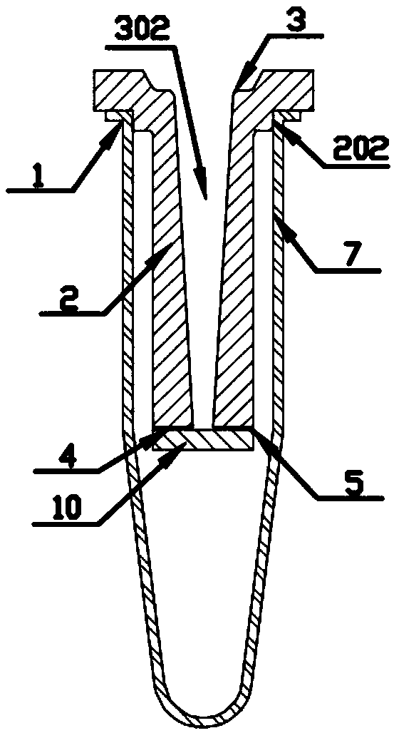
[0041] Embodiment 1, with reference to figure 1 , Figure 2-1 , Figure 2-2 , image 3 , Pic 4-1 , Figure 4-2 , a droplet preparation chip device in a tube, including a reaction tube 1 and a droplet generation chip 2 assembled therewith, the reaction tube 1 adopts a centrifuge tube or a PCR tube commonly used in a laboratory, and cooperates with the droplet generation chip 2 to complete droplet generation, It also serves as a container for droplet collection and reaction. The following is an example of a 0.5mL centrifuge tube; the droplet generation chip 2 is a stepped cylindrical structure, which is used for droplet preparation after being assembled with the reaction tube 1; The droplet generation chip 2 has a plurality of branch microchannels 4 with the same size and structure connected to the reagent inlet 3. The branch microchannels 4 are parallel to the bottom of the droplet generation chip 2 and radially distributed from the center of the chip to the outside. The b...

Embodiment 2

[0050] Embodiment 2, with reference to Figure 5 , Figure 6-1 and Figure 6-2 , a chip device for preparing liquid droplets in a tube, including a reaction tube 1 and a droplet generating chip 2; in order to realize large-scale liquid droplet preparation and mass production of chip devices, the reaction tube 1 passes through the first connecting plate structure 101 in eight The reaction tube 1 adopts a flat-bottomed truncated conical tube to reduce the consumption of continuous phase reagents; at the same time, the droplet generation chip 2 is also made in eight rows through the second connecting plate structure 201, and is connected with the The reaction tube 1 is assembled to prepare 8 groups of dispersed phase reagents 9 droplets at the same time. There is a distance between the bottom of the droplet generation chip 2 and the bottom of the reaction tube 1 for the storage of droplets 6 or continuous phase reagents 8 .

[0051] The reaction tube 1 and the droplet generatio...


PUM


Abstract

An in-tube liquid drop preparing chip device comprises a reaction tube and a liquid drop generation chip, wherein the liquid drop generation chip comprises a reagent inlet and a plurality of branch micro-channels with the consistent sizes and structures; the branch micro-channels are connected with the reagent inlet; the branch micro-channels are parallel to the bottom of the liquid drop generation chip and are distributed in an outwards scattered manner from the center of the chip; outlets of the branch micro-channels are positioned at the outer edge of the side wall of the liquid drop generation chip, and a spraying opening structure is formed to be used for preparing liquid drops; the reaction tube is loaded with a continuous phase reagent during preparation of the liquid drops; in a whole liquid drop preparation process, the continuous phase reagent fully submerges and soaks the branch micro-channels and the spraying opening structure of the liquid drop generation chip, and a dispersion phase reagent is loaded through a reagent inlet, arrives at the position of the spraying opening structure via the branch micro-channels under the effect of pressure and then is broken to form liquid drops; and the integration performance of the device is improved, a liquid drop generation process is simplified, external pressure drive is relieved, the cost and complexity of the system are controlled, the liquid drop preparation frequency is increased to a maximum extent, and analysis requirements of different applications are met.

Description

technical field [0001] The invention belongs to the technical field of biochemical microfluidics, and in particular relates to a chip device for preparing liquid droplets in a tube. Background technique [0002] In the field of biochemical microfluidic analysis for enzyme synthesis and its activity analysis, droplet digital PCR and high-throughput screening of cells, droplet microfluidics technology has experienced rapid development, and microdroplets are often used as nanoliter or picoliter Even femtoliter-level discrete biochemical reaction vessels have great advantages in the accuracy, sensitivity and repeatability of analysis and detection. In addition, the advantages of automation, easy integration, and high throughput of microfluidic technology can also greatly improve the sensitivity and efficiency of biochemical analysis. Droplets are usually composed of immiscible continuous phase and dispersed phase reagents, and the dispersed phase is separated into discrete micr...

Claims


Application Information

Patent Timeline
Patent Type & Authority Applications(China)
IPC IPC(8): B01L3/00
CPCB01L3/5027B01L2300/0861B01L2300/161B01L2200/10
Inventor 赵书豪胡飞
Owner XI AN JIAOTONG UNIV
Learn More