

Double-resonant-cavity coupled all-fiber Q-switched mode-locked pulse laser
A mode-locked pulse and dual-cavity technology, which is applied in the fields of laser technology, fiber optics and nonlinear optics, can solve the problem of insufficient single pulse energy of mode-locked lasers, insufficient narrow pulse width of Q-switched lasers, and poor anti-interference ability of the environment, etc. problems, to achieve the effect of easy industrial production and application, compact structure, and strong environmental interference ability
- Summary
- Abstract
- Description
- Claims
- Application Information
AI Technical Summary
Problems solved by technology
Method used
Image

Examples
Embodiment 1
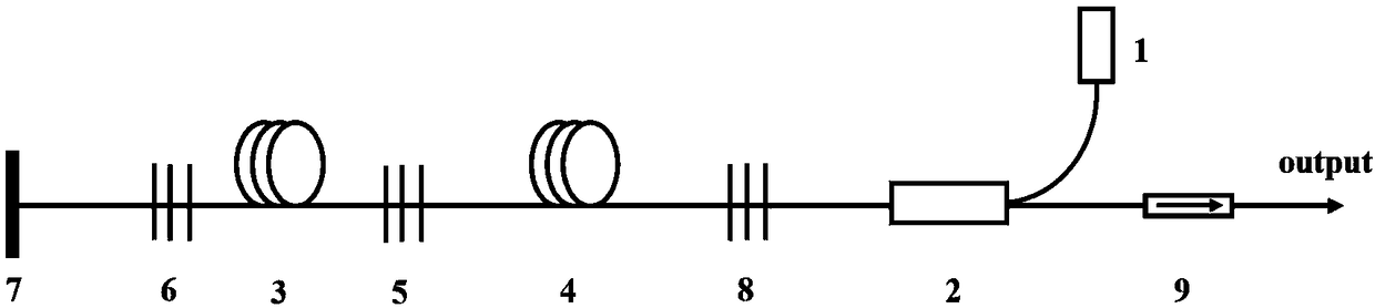
[0037] Such as figure 1 As shown, a dual-cavity coupled all-fiber Q-switched mode-locked pulse laser includes a pumping device, a laser resonator, a gain fiber, a saturable absorbing element, and a laser output device. The pumping device includes a pumping source 1, an optical fiber A beam combiner 2 and a wavelength division multiplexer 10; the laser resonator includes a first reflective fiber Bragg grating 5, a second reflective fiber Bragg grating 6, a semiconductor saturable absorbing mirror (SESAM) 7, a third reflective fiber Bragg grating Grating 8, total reflection mirror 13; gain fiber includes first gain fiber 3 and second gain fiber 4; laser output device includes optical isolator 9, circulator 11 and fiber beam splitter 12.
[0038]When the linear cavity structure is adopted, the first reflective fiber Bragg grating 5 and the second reflective fiber Bragg grating 6 constitute an inner resonant cavity, and the first gain fiber 3 is included in the inner resonant cavi...
Embodiment 2
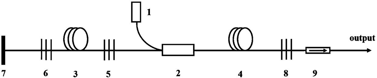
[0045] Such as figure 2 As shown, the basic structure is similar to that of Embodiment 1, except that the pump source 1 and the fiber combiner 2 are placed between the first reflective fiber Bragg grating 5 and the second gain fiber 4. This can reduce the requirements of the laser output on the device to a certain extent.
Embodiment 3
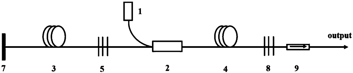
[0047] Such as image 3 shown. 1 in the figure is the pump source, which can be a semiconductor laser diode with a center wavelength of 976nm; 2 is an optical fiber combiner, and a (2+1)×1 pump signal combiner can be used, such as 6 / 125 or 10 / 125 type; 3 and 4 are rare-earth-doped optical fibers, which can be ytterbium-doped optical fibers with a core diameter of 6 μm or 10 μm produced by Nufern Company in the United States; 5 and 8 are reflective fiber Bragg gratings, and total reflection or partial reflection gratings can be selected , the reflectivity is between 0 and 1; 7 is a broadband semiconductor saturable absorber mirror, and other broadband reflective saturable absorbers can also be selected; 9 is an optical isolator, a polarization-independent optical isolator is optional.
[0048] The pump light generated by the pump source 1 enters the second gain fiber 4 through the pump end of the fiber combiner 2, and then reaches the third reflective fiber Bragg grating 8, w...
PUM
| Property | Measurement | Unit |
|---|---|---|
| Center wavelength | aaaaa | aaaaa |
| Diameter | aaaaa | aaaaa |
Abstract
Description
Claims
Application Information