Uniform heating device for vapor deposition and vapor deposition furnace

A technology of uniform heating and vapor deposition, applied in gaseous chemical plating, metal material coating process, coating and other directions, can solve the problems of slow heating speed, uneven heating, uneven heating of workpiece, etc., to avoid uneven heating, Ensure uniformity and ensure the effect of balance

Active Publication Date: 2020-09-01
SUZHOU SICREAT NANOTECH CO LTD
View PDF1 Cites 0 Cited by
  • Summary
  • Abstract
  • Description
  • Claims
  • Application Information

AI Technical Summary

Problems solved by technology

[0007] First, since the heater is located outside the reaction chamber, multiple heat transfer processes are required to heat the interior of the reaction chamber and the workpiece. Each process will have a large heat consumption loss, so a large amount of energy is consumed, and there is energy consumption. The problem of high and relatively slow heating speed
[0008] On the other hand, in order to obtain a relatively uniform heat distribution, it is necessary to scientifically and effectively arrange the heater or radio frequency coil, which is demanding and difficult. Once the radio frequency coil or heater is not properly arranged, it will lead to heating of the graphite tube or reaction chamber. Uneven, and the uneven heating of the graphite tube will inevitably lead to uneven heating of each area in the processing chamber, which will lead to the problem of uneven heating of the workpiece
[0009] At the same time, when multiple workpieces are processed at the same time, due to the difference in heat distribution in different regions of the graphite reaction chamber, the uniformity of heating of each workpiece cannot be guaranteed, so that the film formation quality of each workpiece cannot be guaranteed; in addition, when there is When the workpiece is heated unevenly, it cannot be effectively compensated by adjusting the heat output by the heater

Method used


Image

  • Uniform heating device for vapor deposition and vapor deposition furnace
  • Uniform heating device for vapor deposition and vapor deposition furnace
  • Uniform heating device for vapor deposition and vapor deposition furnace

Examples


Embodiment Construction

[0043] Objects, advantages and features of the present invention will be illustrated and explained by the following non-limiting description of preferred embodiments. These embodiments are only typical examples of applying the technical solutions of the present invention, and all technical solutions formed by adopting equivalent replacements or equivalent transformations fall within the protection scope of the present invention.

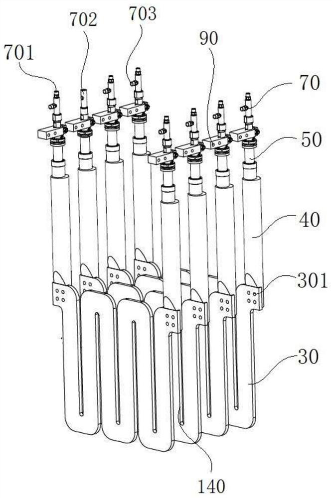
[0044] The invention discloses a uniform heating device for vapor deposition, such as the attached figure 2 As shown, at least two heating plates 30 arranged in gaps are included, and the projections of the heating plates 30 on the same projection plane parallel to them coincide, and the gap between adjacent heating plates 30 forms a heating plate for placing the workpiece 1. Space 140, two ends of each heating plate 30 are respectively connected to a graphite electrode 40, each graphite electrode 40 is connected to a copper electrode 50, and the ou...


PUM


Abstract

The invention discloses a vapor deposition uniform heating device and a vapor deposition furnace. The vapor deposition uniform heating device comprises at least two heating plates arranged at intervals, the heating plates coincide with projections on a same projection surface parallel to the two heating plates, heating space used for placing workpieces is formed in gaps between the adjacent heating plates, graphite electrodes are separately connected to the two ends of each heating plate, and each graphite electrode is connected with a copper electrode used for connecting power supply. The design is ingenious, the heating space used for placing workpieces is formed in the gaps between the two adjacent heating plates, the two heating plates directly heat the workpieces from two opposite directions simultaneously, on the one hand, the higher heating efficiency is achieved, thermal loss in the thermal transmission process is reduced, and the reduction of energy consumption is facilitated;and meanwhile, two surfaces are heated simultaneously, the guarantee of heating homogeneity is facilitated, and nonuniform heating of the workpieces is avoided.

Description

technical field [0001] The invention relates to the field of vapor deposition, in particular to a uniform heating device for vapor deposition and a vapor deposition furnace. Background technique [0002] Chemical Vapor Deposition (CVD) refers to the process of introducing the gaseous or liquid reactant vapor containing the film elements and other gases required for the reaction into the reaction chamber, and a chemical reaction occurs on the surface of the substrate to form a film. [0003] The CVD chemical vapor deposition furnace uses the principle of chemical vapor deposition (Chemical Vapor Deposition) to heat the substances involved in the chemical reaction to a certain process temperature, and under the gravitational force generated by the vacuum pump pumping system, it is led to the deposition chamber for reaction and deposition. , to generate a new solid thin film substance. [0004] as attached figure 1 The chemical vapor deposition furnace shown generally include...

Claims


Application Information

Patent Timeline
Patent Type & Authority Patents(China)
IPC IPC(8): C23C16/46C23C16/52C23C16/455
CPCC23C16/45578C23C16/46C23C16/52
Inventor 张立国崔志国鞠涛范亚明张泽洪张宝顺
Owner SUZHOU SICREAT NANOTECH CO LTD
Why Eureka
Try Eureka