Sintering ore air draft type circulating cooling system and process thereof

A circulating cooling system and a drafting technology, applied in the field of ironmaking, can solve the problems of low boiler thermal efficiency, difficult to efficiently recover and utilize sensible heat of sintered ore, and high power consumption of fans

Pending Publication Date: 2019-03-05
ZHONGYE-CHANGTIAN INT ENG CO LTD
View PDF15 Cites 4 Cited by
  • Summary
  • Abstract
  • Description
  • Claims
  • Application Information

AI Technical Summary

Problems solved by technology

No matter which cooling method is used, the cooling machine has problems such as large air leakage rate, high fan power consumption, low sensible heat recovery rate, and low boiler thermal efficiency.
In other words, in the current environment where the market has increasingly stringent requirements for energy saving and green manufacturing in sinter production, the original equipment structure has been difficult to achieve efficient recovery and utilization of sinter sensible heat

Method used


Image

  • Sintering ore air draft type circulating cooling system and process thereof
  • Sintering ore air draft type circulating cooling system and process thereof
  • Sintering ore air draft type circulating cooling system and process thereof

Examples


Embodiment 1

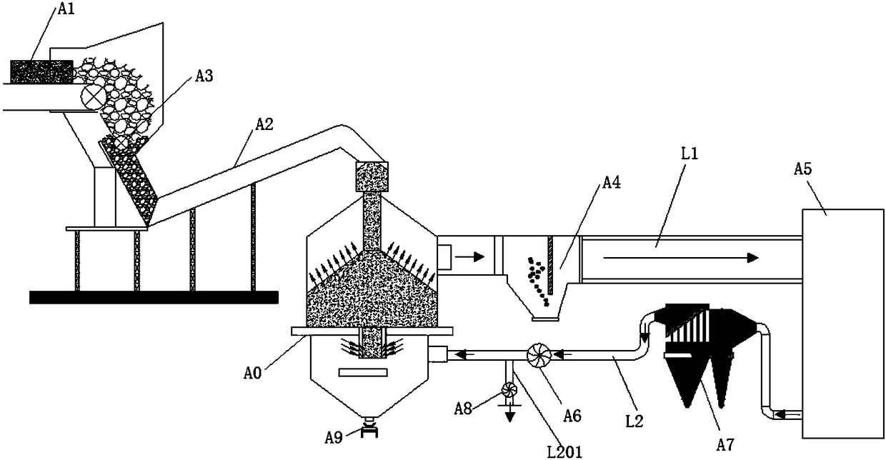
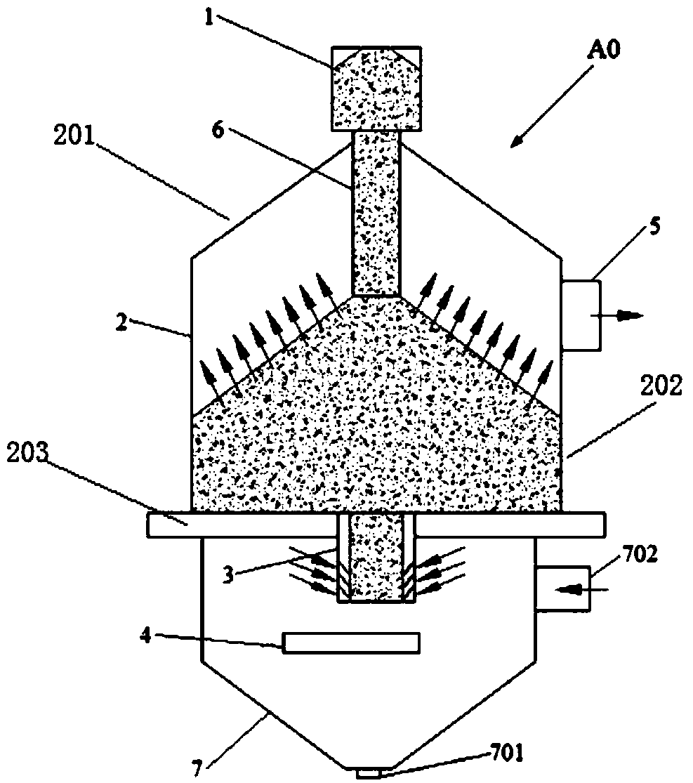
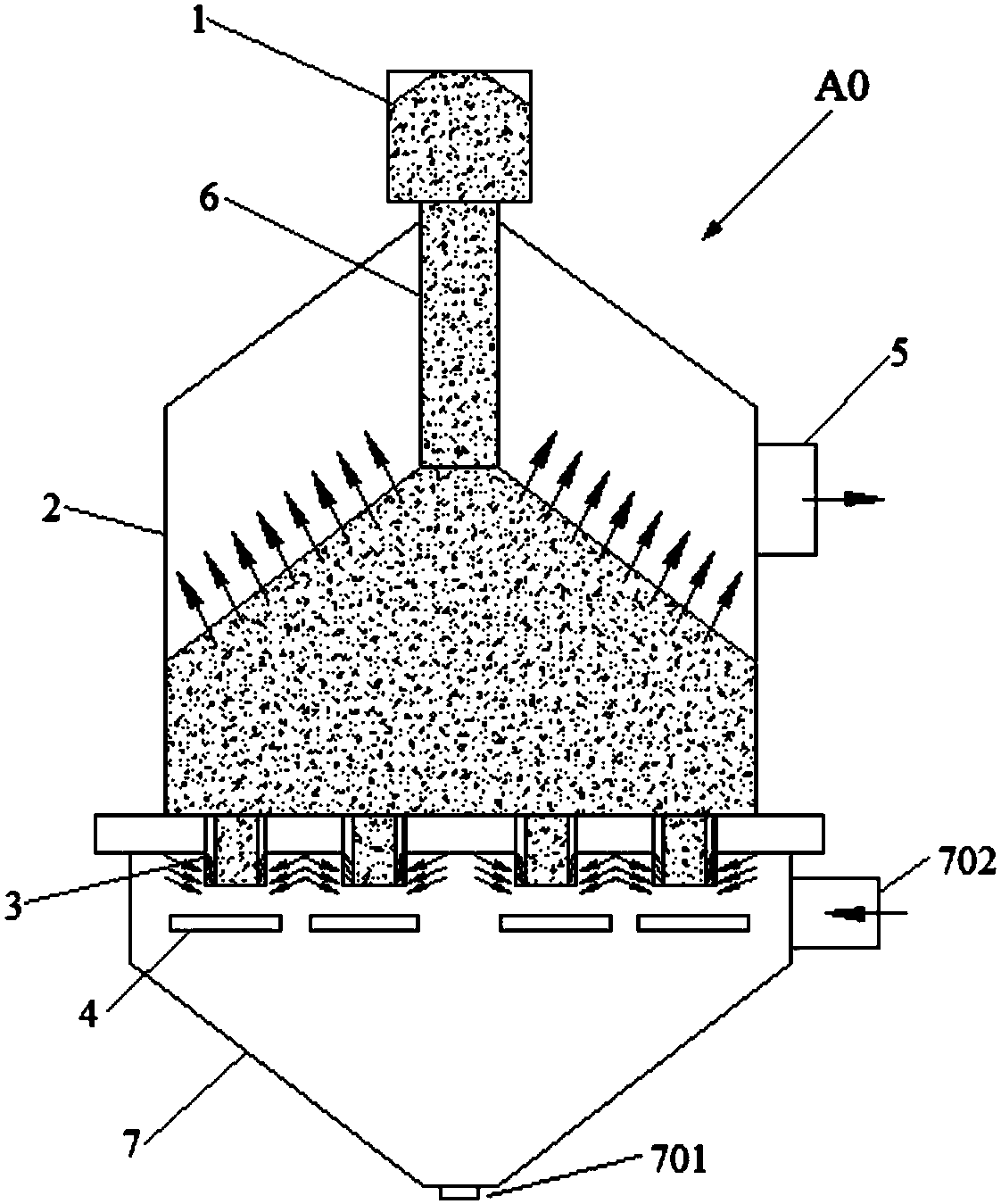
[0157] like figure 1 As shown, a sinter ventilation circulation cooling system, the system includes ventilation vertical cooling furnace A0, waste heat boiler and power generation system A5, circulation exhaust fan A6, hot air delivery channel L1, cold air delivery channel L2. Among them: the draft vertical cooling furnace A0 includes a silo 1, a tower body 2, an air inlet and discharge device 3, a discharge device 4, and a discharge chute 7. The tower body 2 includes a tower top 201 , a tower wall 202 and a tower bottom 203 . The tower top 201 is arranged on top of the tower wall 202 . The tower bottom 203 is provided at the bottom of the tower wall 202 . The feed bin 1 is arranged above the tower top 201 and communicates with the inside of the tower body 2 . The air intake and discharge device 3 is arranged below the tower bottom 203 and communicates with the inside of the tower body 2 . The discharge device 4 is arranged below the air intake and discharge device 3 . Th...

Embodiment 2

[0159] Repeat Example 1, except that the system further includes: sintering machine A1, hot sinter conveying device A2. The discharge port of the sintering machine A1 is connected to the feed port of the silo 1 through the hot sinter conveying device A2. The system also includes: Crusher A3; Crusher A3 is a single-roll crusher; Crusher A3 is set at the discharge port of sintering machine A1, and the discharge port of Crusher A3 is connected to the silo through hot sinter conveying device A2 1 feed port.

Embodiment 3

[0161] Embodiment 2 is repeated, except that the first dust remover A4 is provided on the hot air conveying channel L1. A second dust collector A7 is also provided on the cold air conveying channel L2. The second deduster A7 is arranged upstream of the circulation exhaust fan A6.


PUM


Abstract

Provided is a sintering ore air draft type circulating cooling system. The system comprises an air draft type vertical cooling furnace, a waste heat boiler and power generation system, a circulating exhaust fan, a hot air conveying channel and a cold air conveying channel, wherein the air draft type vertical cooling furnace comprises a material bin, a tower body, an air inlet discharging device, adischarging unit and a discharging chute; an air draft type hot air outlet is formed in the upper portion of the tower body; a cold air inlet is formed in the side wall of the discharging chute; theair draft type hot air outlet is connected with an air inlet of the waste heat boiler and power generation system through the hot air conveying channel; and an air outlet of the waste heat boiler andpower generation system is connected with a cold air inlet through the cold air conveying channel. The cooling system and a cooling process can effectively cool sintering ores and are low in air leakage, and at the same time, after cooling air is subjected to heat exchange with the sintering ores, waste heat can be totally used to achieve circulation.

Description

technical field [0001] The invention relates to a sinter cooling system, a sinter cooling waste heat utilization system and a process thereof, in particular to a sinter ventilation circulation cooling system and a process thereof, which belong to the field of ironmaking and environmental protection. Background technique [0002] In recent years, with the increasingly tense relationship between energy consumption and environmental protection in my country, energy conservation and environmental protection have been valued by the whole society, making it a key measure to establish a resource-saving and environment-friendly society. Energy conservation and environmental protection work involves all aspects. Energy conservation and environmental protection in the industrial field is the focus and difficulty of energy conservation and environmental protection work, especially for the steel industry with high energy consumption and heavy environmental pollution. The energy consumpt...

Claims


Application Information

Patent Timeline
Patent Type & Authority Applications(China)
IPC IPC(8): F27D17/00F27D9/00
CPCF27D9/00F27D17/004F27D2009/0005Y02P10/25
Inventor 贺新华张震叶恒棣温荣耀
Owner ZHONGYE-CHANGTIAN INT ENG CO LTD
Why Eureka
Try Eureka