Low-power-loss laser pumping source system

A laser pumping and electrical loss technology, applied in lasers, laser parts, laser monitoring devices, etc., can solve problems such as reducing output current stability, burning out power tubes, and reducing overall efficiency, improving safety, preventing The effect of repeated actions

Inactive Publication Date: 2019-03-08
JILIN UNIV
View PDF8 Cites 0 Cited by
  • Summary
  • Abstract
  • Description
  • Claims
  • Application Information

AI Technical Summary

Problems solved by technology

In this loop, the sum of the voltage drop borne by the power transistor Q1, the voltage drop borne by the sampling resistor Rs1, and the voltage drop borne by the laser diode is equal to the power supply voltage VCC (fixed value), when the set driving current changes from large to small , the voltage at both ends of the laser diode and the voltage at both ends of the sampling resistor Rs1 are correspondingly reduced, and the power transistor Q1 is a nonlinear device, which will actively bear the excess voltage to keep the sum of the three voltages equal to VCC, which will cause the circuit The generated electric power is more converted into the tube consumption of the power tube Q1, that is to say, as the set driving current decreases, the output power of the power control module decreases, but the power loss of the power control module itself increases, which means On the one hand, the overall efficiency of the system will drop sharply. On the other hand, with the increase of the tube consumption of the power tube Q1, the heat generated by it will increase, and the temperature of the system will increase, and the increase of temperature will bring about more serious problems. Consequences: Reduce the stability of the output current and bring the risk of burning out the power tube
[0005] In addition, patent 2016108010570 does not have the function of overcurrent protection. Once a certain control unit fails and the current value output to the butterfly laser module exceeds the maximum safe current value that the butterfly laser can withstand, it is easy to burn the butterfly laser. Bad

Method used


Image

  • Low-power-loss laser pumping source system
  • Low-power-loss laser pumping source system
  • Low-power-loss laser pumping source system

Examples


Embodiment 1

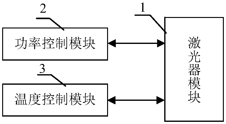
[0037] Embodiment 1 Overall structure of the system

[0038] Such as figure 1 As shown, the system structure includes a laser module 1, a power control module 2, and a temperature control module 3. Both the power control module 2 and the temperature control module 3 are connected to the laser module 1, and the power control module 2 provides driving current to the laser module 1, and the temperature control module Module 3 is responsible for controlling the working temperature of the laser module to make it work at a constant temperature.

Embodiment 2

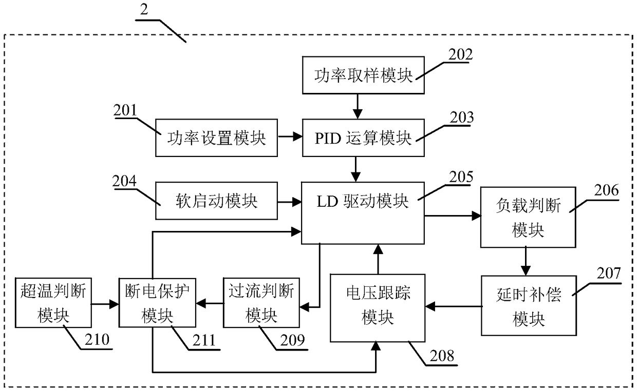
[0039] Embodiment 2 The structure of the power control module 2 of the present invention

[0040] The structure of the power control module 2 is as figure 2 As shown, it includes a power setting module 201, a power sampling module 202, a PID calculation module 203, a soft start module 204, an LD driver module 205, a load judging module 206, a delay compensation module 207, a voltage tracking module 208, and an overcurrent judging module 209 , an over-temperature judging module 210 and a power-off protection module 211. The required power is set by the power setting module 201, and the power sampling module 202 samples the output optical power through the photodiode (PD) integrated in the laser module 1 and converts it into a voltage, and then performs PID calculation with the voltage set by the power setting module 201 In the module 203, the difference is calculated and the PID operation is performed. The result of the operation is output to the LD drive module 205 and contro...

Embodiment 3

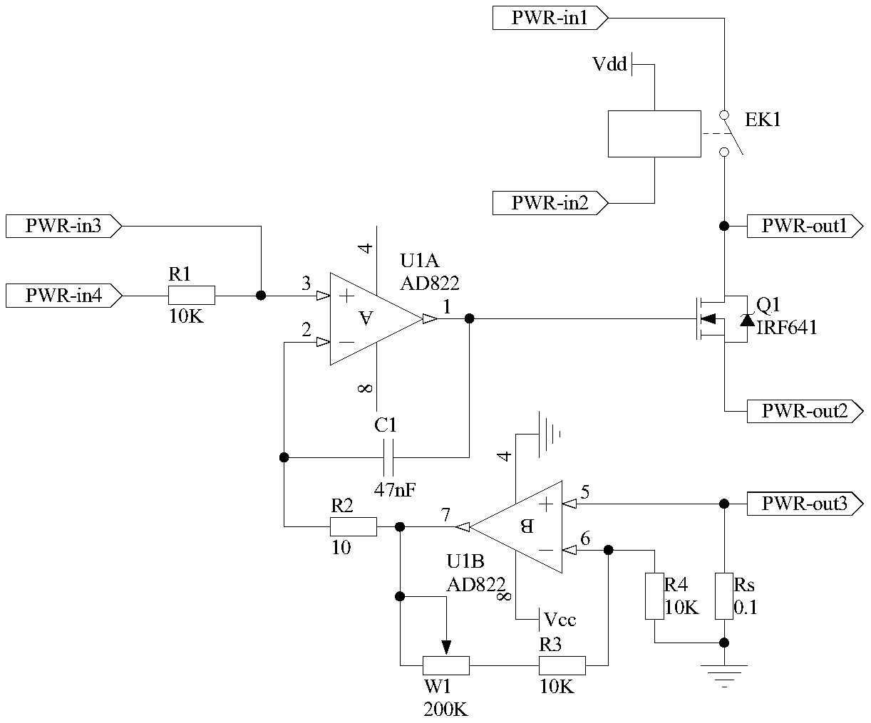
[0044] Embodiment 3 The load judging module of the present invention

[0045] The structure of the load judging module 206 of the present invention is as follows Figure 4As shown: the non-inverting input terminal of the operational amplifier U2A is used as the first input terminal of the load judgment module 206, which is denoted as port Vjdg-in1, and is connected to the port PWR-out1 of the LD driver module 205, and the inverting input terminal of the operational amplifier U2A is connected to the The output terminal of operational amplifier U2A is connected to one end of resistor R5, the other end of resistor R5 is connected to one end of resistor R6 and the same-inverting input terminal of operational amplifier U3A, the other end of resistor R6 is grounded, and the output terminal of operational amplifier U3A is connected to the in-phase input terminal of operational amplifier U3A. One end is connected to one end of the resistor R9, the other end of the resistor R8 is conne...


PUM


Abstract

The invention discloses a low-power-loss laser pumping source system, and belongs to the technical field of electronic equipment. The system structurally comprises a laser module (1), a power controlmodule (2) and a temperature control module (3); and the main structure of the power control module (2) comprises a load judging module (206), a delay compensation module (207), a voltage tracking module (208) and a power-off protection module (211). When the system works in different output power, the minimum power loss can be kept, so that the overall efficiency of the system is improved.

Description

technical field [0001] The invention belongs to the technical field of electronic equipment, and in particular relates to a laser pumping source system with low electric loss. Background technique [0002] With its low threshold, high power, high beam quality, good reliability, compact structure and good heat dissipation, fiber lasers are widely used in laser fiber communication, laser space long-distance communication, industrial shipbuilding, automobile manufacturing, laser engraving, Laser marking, laser cutting, printing roll, metal and non-metal drilling / cutting / welding (brazing, quenching, cladding and deep welding), military defense security, medical equipment and other fields. A fiber laser is a laser that uses a rare earth-doped fiber as a gain medium. Fiber lasers are developed on the basis of fiber amplifiers and are composed of three basic elements: pump source, rare earth element-doped fiber, and resonant cavity. The working principle is: the photons at the pum...

Claims


Application Information

Patent Timeline
Patent Type & Authority Applications(China)
IPC IPC(8): H01S3/09H01S3/00H01S3/13
CPCH01S3/0014H01S3/09H01S3/1305
Inventor 霍佳雨黎钧中郭玉彬孙雅东李志军孙铁刚高博
Owner JILIN UNIV
Why Eureka
Try Eureka