

Integrated mixing machine for building construction concrete mixing plant
A technology for building construction and mixer, applied in mixing plants, cement mixing devices, clay preparation devices, etc., can solve the problems of low mixing efficiency and poor mixing effect, etc.
- Summary
- Abstract
- Description
- Claims
- Application Information
AI Technical Summary
Problems solved by technology
Method used
Image

Examples
Embodiment Construction
[0028] Below in conjunction with accompanying drawing, the present invention will be further described, embodiment is exemplary, only for revealing and explaining the present invention, in order to fully understand the present invention, but does not therefore limit the present invention to described implementation within the scope of the example.
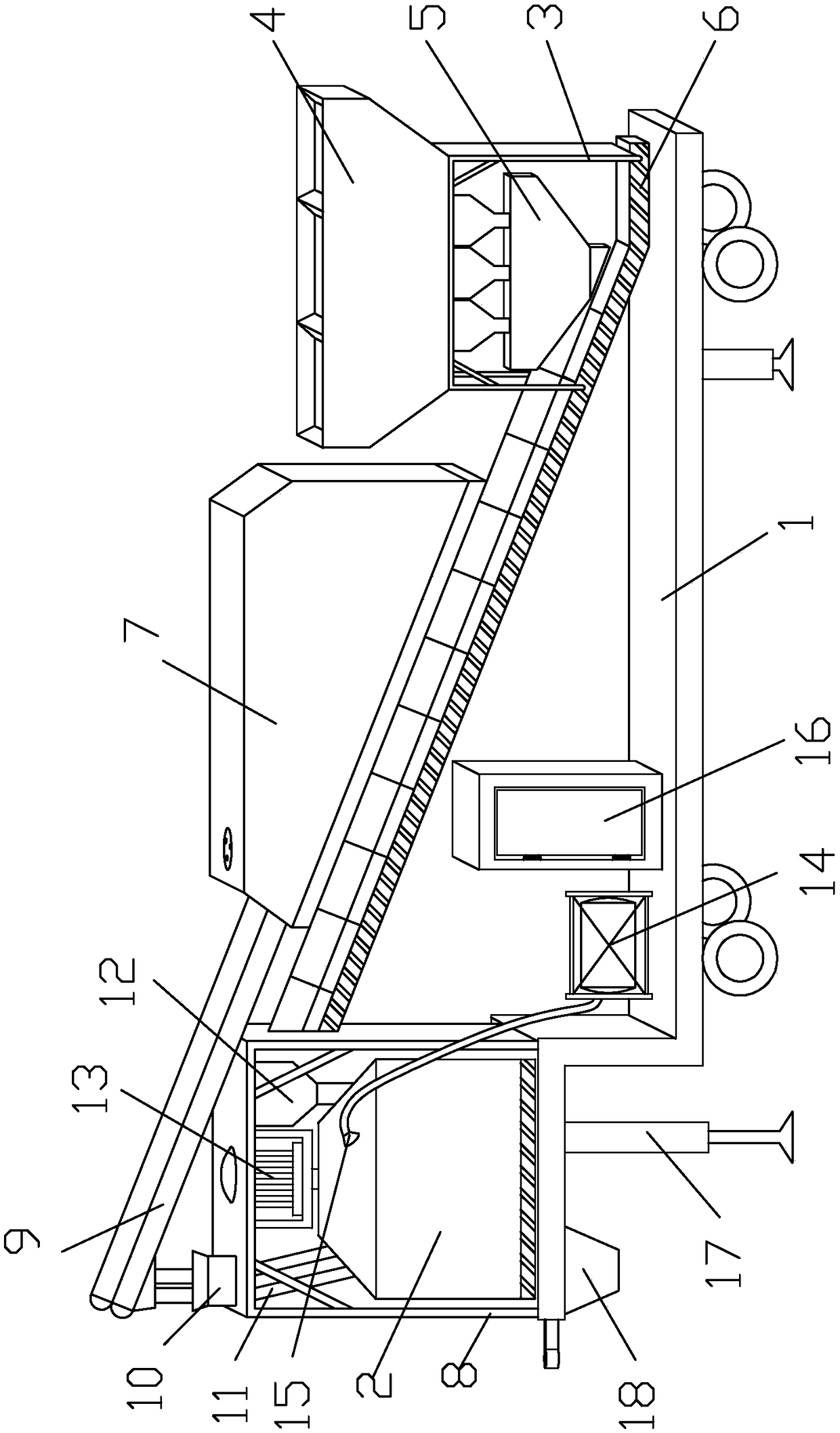
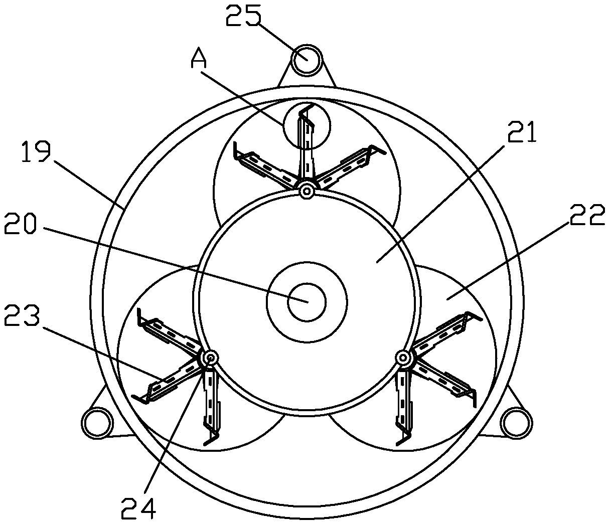
[0029] An integrated mixer for a building construction concrete mixing station, comprising a mixer 2 arranged on a movable body 1, the mixer 2 includes a main turntable 12 driven by a main mixing motor 13, and the main turntable 12 is provided with circumferentially distributed 3 stirring components; and the stirring components are driven by a corresponding pair of stirring motors 27, and the rotation direction of the stirring components is opposite to that of the main turntable 12.
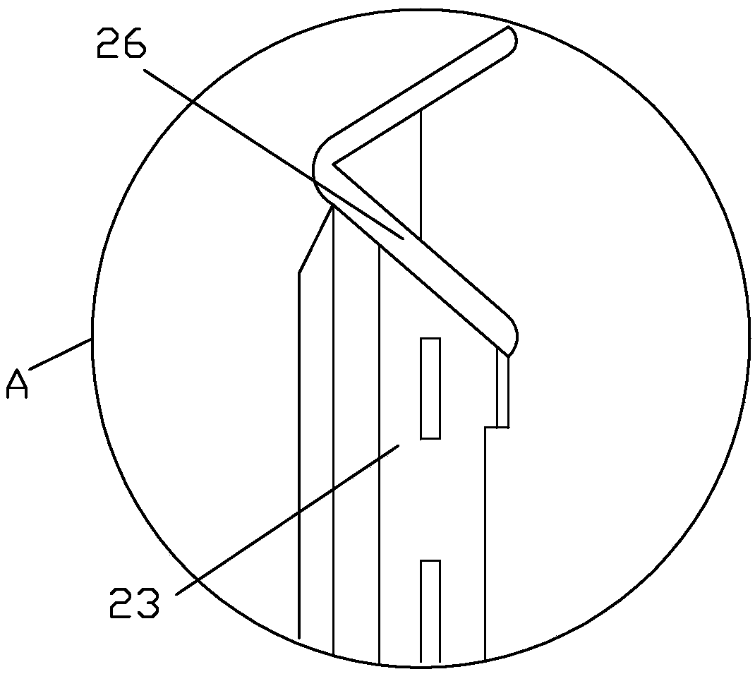
[0030] Wherein, the stirring member includes a rotating shaft 24, the upper end of which is fixedly connected with the output shaft of the auxiliary ...
PUM
 Abstract
Description
Claims
Application Information