
Dual-channel miniature Raman spectrometer

By adopting a dual-channel micro design in the Raman spectrometer, including a near-infrared or near-ultraviolet laser source and an area array detector, combined with wireless data transmission, the problems of low sensitivity and poor portability of the existing Raman spectrometer are solved, and high sensitivity is achieved and portable miniature Raman spectrometer, suitable for rapid detection and real-time interpretation of trace substances.

Inactive Publication Date: 2019-03-22
ULSEE
View PDF5 Cites 8 Cited by
  • Summary
  • Abstract
  • Description
  • Claims
  • Application Information

AI Technical Summary

Problems solved by technology

However, because Raman spectroscopy is a scattering spectrum rather than an absorption spectrum, its sensitivity is not high. If the scattering cross section of the measured substance is at 10 -27 (cm 2 / melecule.srd) are often not detected, so the existing near-infrared and visible Raman spectrometers can only detect milligram-level substances that are visible to the eyes, but cannot detect trace substances that are invisible to the eyes
In addition, the traditional Raman uses a spherical microscopic objective lens, and the too small focal point will detonate when detecting explosives; for convenience, they all use optical fiber coupling slits to cause a large loss of light energy; the F number used in the spectrometer is 4. The large reflector C-T structure has a small luminous flux; the detector is a unit linear array CCD or CMOS, and the light energy passing through the vertical direction of the slit is wasted; the instrument uses a power-consuming touch screen (because it is not a computer, it can only display Curve can not be interpreted) or very big notebook, carry and use all very inconvenient; The purpose of the present invention is to overcome all these shortcoming

Method used


Image

  • Dual-channel miniature Raman spectrometer
  • Dual-channel miniature Raman spectrometer
  • Dual-channel miniature Raman spectrometer

Examples


Embodiment 1

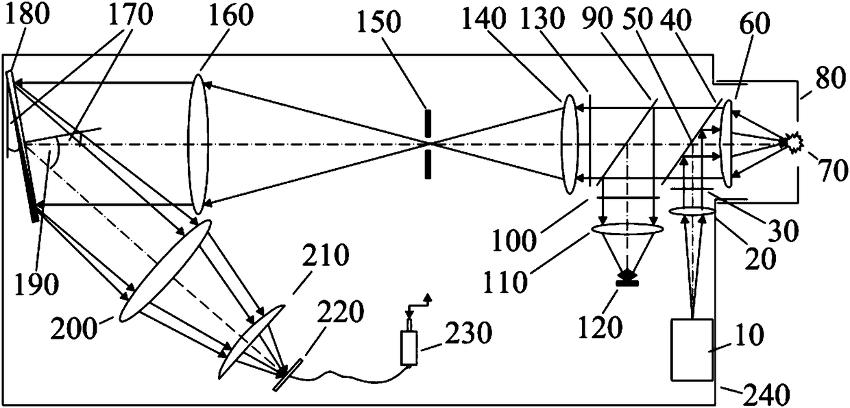
[0027] Such as figure 1 As shown, the laser diode 10 emits near-infrared light with a wavelength of 785nm, and the light spot is a rectangle of 0.2mmx1mm. The collimator 20 with a longer focal length is adjusted to form parallel light, and the narrow-band filter 30 limits the light beam to about 785nm. To the central part 50 of the first beam splitter 40, the laser light is almost totally reflected and focused onto the target 70 by the cylindrical objective lens 60 with a short focal length, and the illuminated point is in the Z direction (perpendicular to the optical axis of the paper surface and the X direction ) is compressed by the ratio of the focal length of the collimator lens to the focal length of the objective lens. The Y direction (perpendicular to the optical axis along the paper surface) remains unchanged at 1mm, so it is a rectangle with a shorter Z direction and a longer Y direction. The diameter of the objective lens It is only 1 / 4" or 6.35mm, and the size of t...


PUM

PropertyMeasurementUnit
wavelengthaaaaaaaaaa
heightaaaaaaaaaa
percent by massaaaaaaaaaa

Abstract

The invention discloses a dual-channel miniature Raman spectrometer, which comprises a near infrared laser diode or a near ultraviolet laser transmitter, a laser beam expanding collimator, an anti-laser laser and Raman light transmission first beam splitter, a zooming and non-zooming cylindrical surface or spherical surface objective lens, an anti-laser Ranman light transmission second beam splitter, a relay optical system, a narrow slit, two spectrum forming lenses, a line array or surface array CCD or CMOS detector, a GPS, and a data processing and wireless receiving and sensing system in sequential connection. After the photo is taken on a target in a laser channel or the sample measurement by optical axis alignment at the Raman channel, data is sent to a mobile phone and a cloud computer in a wireless way for processing of spectrum separation, wave peak finding, spectral database building, substance recognition and the like; the conclusion is fast obtained. The size of the spectrometer is small; the spectrometer can be conveniently carried and used; the measurement result can be seen in places with the Internet; the sensitivity and the resolution ratio are higher than those ofsimilar products.

Description

technical field [0001] The invention relates to a Raman spectrometer, in particular to a dual-channel miniature Raman spectrometer involving on-site measurement of various residual substances. Background technique [0002] Raman spectrum (Raman spectrum) is a kind of scattering spectrum. In 1928, C.V.Raman (Raman) discovered that when light passes through a transparent medium and is scattered by molecules, the frequency changes due to energy gain or loss. This phenomenon is called Raman scattering. In the scattering spectrum of a transparent medium, the frequency and the incident light frequency υ 0 The same component is called Rayleigh scattering; frequency symmetric distribution in υ 0 The spectral line or spectrum υ on both sides 0 ±υ is called Raman scattering or Raman spectrum, where υ 0 The scattering of -υ is called Stokes scattering, which is easy to occur and has been studied more; υ 0 The scattering of +υ is called anti-Stokes scattering, which is not easy to ...

Claims


Application Information

Patent Timeline
Patent Type & Authority Applications(China)
IPC IPC(8): G01N21/65G01J3/44
CPCG01J3/44G01N21/65G01N2201/0612G01J3/0208G01J3/0248G01J3/0256G01J3/0264G01J3/10G01J3/2803G01J3/0229
Inventor 张幼文
Owner ULSEE
Learn More