Smoke gas denitration device for combustion machine

A technology of denitrification and gas turbine, which is applied in the direction of dispersed particle separation, chemical instruments and methods, separation methods, etc., can solve the problems of direct emission of flue gas from gas turbines, and achieve the effect of sufficient reaction, thorough reaction, and uniform and smooth flow of flue gas

Inactive Publication Date: 2019-03-29
HUADIAN QINGDAO ENVIRONMENTAL TECHNOLOCY CO LTD
View PDF0 Cites 0 Cited by
  • Summary
  • Abstract
  • Description
  • Claims
  • Application Information

AI Technical Summary

Problems solved by technology

[0003] The main purpose of the present invention is to provide a flue gas denitrification device for gas turbines to solve the problem in the prior art that the flue gas from gas

Method used


Image

  • Smoke gas denitration device for combustion machine
  • Smoke gas denitration device for combustion machine

Examples


Embodiment Construction

[0020] The present invention will be further described below in conjunction with accompanying drawing.

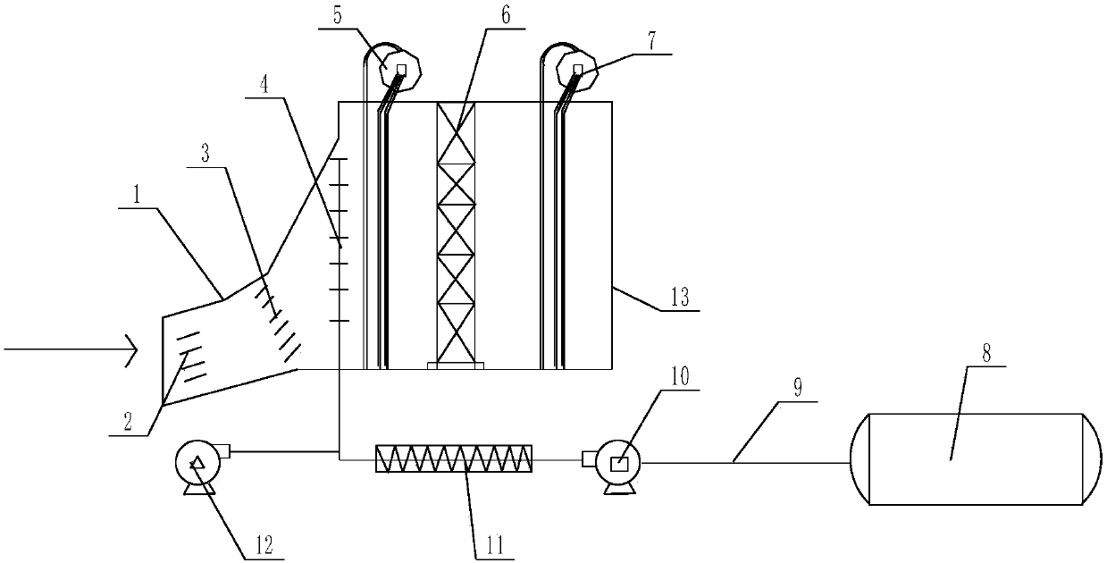
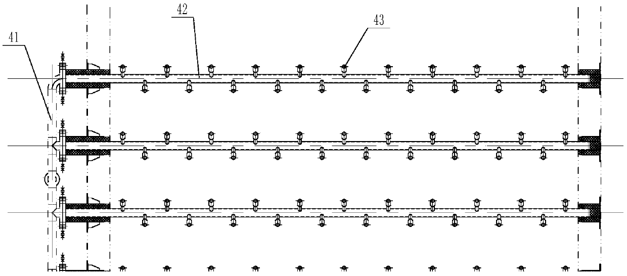
[0021] Such as Figure 1-2 As shown, the gas turbine flue gas denitrification device according to the present invention includes a denitrification reaction device and an ammonia gas delivery device;

[0022] The denitration reaction device includes a reaction shell 13, an ammonia injection grid 4, a heat exchanger 5, and a denitration catalyst module 6; the front end of the reaction shell is connected to the flue 1 of the gas turbine waste heat boiler, and the flue gas flows into the denitration reaction according to the flow direction After the installation, it is discharged after passing through the ammonia injection grid, heat exchanger, and denitration catalyst module;

[0023] The ammonia water delivery device includes an ammonia water storage tank 8, an ammonia water delivery pipe 9, an ammonia water delivery pump 10, an ammonia evaporator 11, and a dilution fan 12; ...


PUM


Abstract

The invention relates to the field of chemical or biological purification of waste gas, in particular to a smoke gas denitration device for a combustion machine. The smoke gas denitration device for the combustion machine comprises a denitration reaction device and an ammonia gas conveying device, wherein the denitration reaction device comprises a reaction casing, an ammonia spraying grid, a heatexchanger and a denitration catalyst module; an ammonia water conveying device comprises an ammonia water storage tank, an ammonia water conveying pipe, an ammonia water conveying pump, an ammonia evaporator and a dilution fan. Compared with the existing smoke outlet denitration device for the combustion machine, the smoke gas denitration device for the combustion machine provided by the invention has the advantages that the smoke gas is subjected to temperature lowering denitration; then, afterheat is recovered; the problems that the combustion smoke gas in the prior art is directly exhausted, and no efficient and reasonable smoke gas denitration device is used for performing denitration treatment on the smoke gas exhausted by the combustion machine are solved; the atmosphere environmentis improved; the ecological stress is relieved.

Description

technical field [0001] The invention relates to the field of chemical or biological purification of waste gas, in particular to a flue gas denitrification device for a combustion engine. Background technique [0002] The high-temperature flue gas from the gas turbine is connected to the boiler through the flue, and the waste heat is recovered and discharged directly into the atmosphere. Since the transition flue distance between the gas turbine and the waste heat recovery boiler in most of the gas turbine power generation projects is very short, it is difficult to directly In the transformation of the middle position, the addition of denitrification in the middle of the waste heat boiler is limited by the space and transformation time, which affects the cost and is extremely difficult. Most of the existing SCR flue gas denitrification technologies are mainly used in coal-fired boilers. At present, gas turbine denitrification is still in the preliminary stage. Due to the grad...

Claims


Application Information

Patent Timeline
IPC IPC(8): B01D53/86B01D53/56
CPCB01D53/8631B01D2251/2062
Inventor 孟凡强王松高春昱秦一鸣孙静楠李新燕徐海龙陈华
Owner HUADIAN QINGDAO ENVIRONMENTAL TECHNOLOCY CO LTD
Why Eureka
Try Eureka