Combustor air distribution device and air distribution method

A technology of air distribution device and burner, which is applied in the combustion method, burner, controlled combustion, etc., can solve the problems of heat pollution, poor combustion efficiency and combustion stability, uneven mixing of air and fuel, etc., to achieve recirculation , to ensure the effect of sufficient and stable combustion

Active Publication Date: 2019-03-29
JIANGSU XCMG CONSTR MASCH RES INST LTD
View PDF11 Cites 6 Cited by
  • Summary
  • Abstract
  • Description
  • Claims
  • Application Information

AI Technical Summary

Problems solved by technology

Since the performance curve of the blower is affected by factors such as combustion, the working state of the induced draft fan, and the system structure, the air supply volume of the blower may even vary greatly under the same damper opening or the same blower speed
[0005] The existing technology has the following defects: the existing technical scheme changes the air supply volume by adjusting the opening of the damper, adjusting the fan speed, etc., and has no air supply volume detection function. And the wind-oil ratio has poor applicability among different stations
[0006] In addition, the existing burner air distribution device has a single function and only has the function of providing combustion-supporting air for combustion
Due to the deflection of the fan outlet air, the existing technical scheme does not rectify the fan outlet air, resulting in uneven mixing of air and fuel during combustion, poor combustion efficiency and combustion stability
During the working process of the mixing station, a large amount of combustible waste gas such as asphalt smoke will be produced. At present, there is no effective way to collect and treat it, and it will be directly discharged into the atmosphere, causing serious environmental pollution.
The temperature of the flue gas discharged into the atmosphere after dust removal in the mixing plant is as high as 100°C. The high-temperature flue gas takes away a lot of heat, wasting energy and causing thermal pollution

Method used


Image

  • Combustor air distribution device and air distribution method
  • Combustor air distribution device and air distribution method
  • Combustor air distribution device and air distribution method

Examples


Embodiment 1

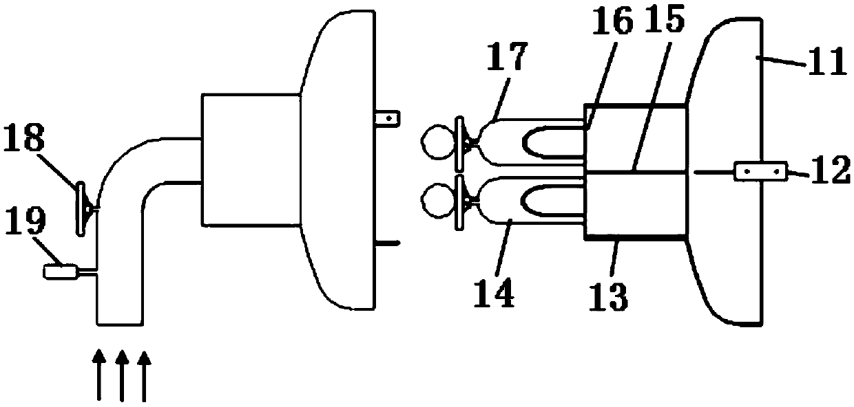
[0068] like figure 1 , figure 2 , image 3 As shown, it is a burner air distribution device, including an air intake device 1 , a blower 2 , and a blower output air volume detection device 3 .

[0069] The outlet of the air inlet device 1 is communicated with the blower 2, and the air outlet of the blower is delivered to the burner;

[0070] The air intake device 1 is provided with a flow detection sensor 19 for real-time detection of the gas flow entering the blower through the air intake device;

[0071] The blower 2 is provided with an air inlet for the intake of fresh air;

[0072] The blower output air volume detection device 3 is used for real-time detection of the output air volume of the blower, that is, the total air supply volume of the air distribution device;

[0073] The blower 2 is provided with a blower output air volume adjusting device for adjusting the output air volume of the blower.

[0074] The air intake device of the air distribution device can hav...

Embodiment 2

[0094] like Figure 4 As shown, a burner air distribution control device includes:

[0095] The acquisition unit is used to acquire information on the rotational speed of the blower, the flow rate of combustible waste gas, the flow rate of the recirculated flue gas, and the total air supply volume of the blower;

[0096] The calculation / comparison unit is used to calculate and obtain the preset value of the total air supply volume, calculate whether the difference between the measured value of the total air supply volume of the blower and the set value of the total air supply volume exceeds the set error value; calculate the measured value of the combustible waste gas flow and Whether the difference between the preset values ​​of the combustible waste gas flow exceeds the set error value; calculate whether the difference between the measured value of the recirculation flue gas flow and the preset value of the recirculation flue gas flow exceeds the set error value; get the cal...

Embodiment 3

[0101] like figure 1 , figure 2 , image 3 , Figure 4 As shown, it is a burner air distribution system, including the above-mentioned burner air distribution device and the above-mentioned burner air distribution control device.

[0102] Further, the detection unit on the air distribution device includes a blower rotation speed detection unit to detect the blower rotation speed information; a combustible waste gas flow detection sensor to detect the combustible waste gas flow information; a recirculation flue gas detection unit to detect Recirculated flue gas volume and flue gas oxygen content information; used to detect and collect information such as blower speed, combustible waste gas flow, recirculated flue gas flow, flue gas oxygen content, and total air supply volume of the blower; and send the information to The control device, the control device receives the blower speed, the combustible waste gas flow rate, the recirculating flue gas flow rate, the oxygen content...


PUM


Abstract

The invention discloses a combustor air distribution device and an air distribution method. The combustor air distribution device comprises an air inlet device, an air blower and an air blower outputair volume detection device, wherein an outlet of the air inlet device communicates with the air blower, air blown by the air blower is conveyed to a combustor, a flow detection sensor is arranged onthe air inlet device, and is used for carrying out real-time detection on the flow of gas entering the air blower through the air inlet device, an air inlet is formed in the air blower and used for sucking fresh air, the air blower output air volume detection device is used for detecting the output air volume of the air blower in real time, namely the total air supply volume of the air distribution device, the air blower is provided with an air blower output air volume adjusting device, and is used for adjusting the output air volume of the air blower, the air inlet device comprises a combustible waste gas pipeline and / or a recycled smoke gas pipeline, and the air blower output air volume detection device is a venturi tube device. Thus, accurate air distribution is achieved, and the combustion efficiency and the stability are guaranteed.

Description

technical field [0001] The invention belongs to the technical field of construction machinery, and relates to an air distribution device and an air distribution method for a burner of a mixing station. Background technique [0002] With the large-scale development of infrastructure construction projects, the demand for asphalt mixture is increasing. Based on the needs of energy saving, emission reduction and environmental protection, the technical performance indicators of asphalt mixing equipment are also getting higher and higher. Most of the burners in the existing asphalt mixing plant use heavy oil as fuel. The blower blows air and the heavy oil burns to generate high-temperature flue gas, which enters the drying system to dry the wet aggregate. The gas is discharged into the atmosphere after the dust removal system, and the temperature of the flue gas discharged into the atmosphere is as high as about 100 ℃. [0003] The combustion efficiency of the burner has a signif...

Claims


Application Information

Patent Timeline
Patent Type & Authority Applications(China)
IPC IPC(8): F23D11/36F23L5/02F23N3/00
CPCF23D11/36F23L5/02F23N3/005F23N2223/10F23N2233/08F23N2235/06Y02E20/34
Inventor 周康赵斌黄建华杨文浩
Owner JIANGSU XCMG CONSTR MASCH RES INST LTD
Why Eureka
Try Eureka