A directional drawing and discharging vacuum melting furnace

A technology of vacuum melting furnace and material type, which is applied in the direction of furnace, crucible furnace, furnace type, etc., can solve the problem of secondary molding, etc., and achieve the effect of increasing the length

Active Publication Date: 2019-11-12
江苏斯力康科技有限公司
View PDF5 Cites 0 Cited by
  • Summary
  • Abstract
  • Description
  • Claims
  • Application Information

AI Technical Summary

Problems solved by technology

[0003] The purpose of the present invention is to provide a directional drawing and discharging type vacuum melting furnace to solve the problem of secondary molding in the use of industrial silicon in the prior art, to realize one-time molding in the vacuum melting process without secondary molding, purpose of cost reduction

Method used


Image

  • A directional drawing and discharging vacuum melting furnace
  • A directional drawing and discharging vacuum melting furnace
  • A directional drawing and discharging vacuum melting furnace

Examples


Embodiment 1

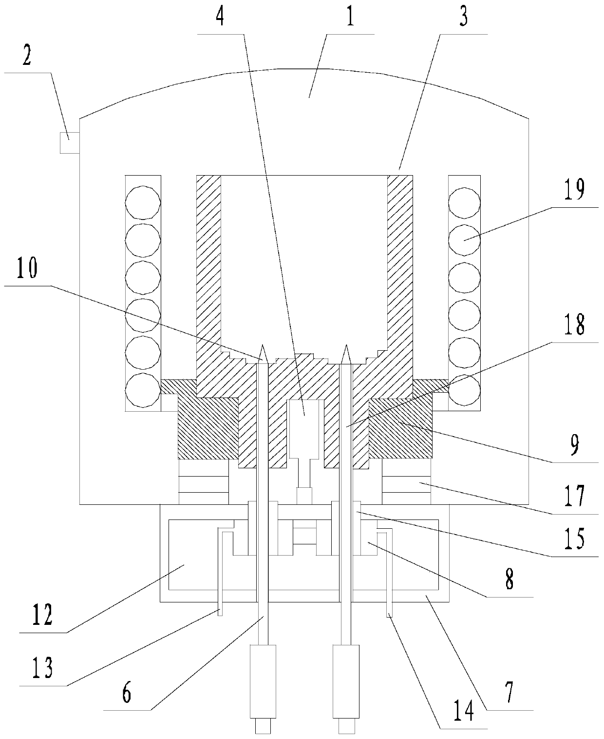
[0029] Such as figure 1 A directional drawing and discharging type vacuum smelting furnace is shown, comprising a furnace body 1 with a vacuum suction port 2, a crucible 3 is arranged in the furnace body 1, an induction heating coil 19 is located outside the crucible 3, and the furnace The inner bottom surface of the body 1 is provided with a pusher 4 with the output end facing upwards, the output end of the pusher 4 is in contact with the bottom of the crucible 3, and the bottom of the crucible 3 is provided with a discharge pipe 5 that runs through the crucible 3, and the discharge pipe 5 is provided with a drawing rod 6, the cross section of the drawing rod 6 matches the cross section of the discharge pipe 5, a crystallization chamber 7 is provided under the furnace body 1, and the inner top surface of the crystallization chamber 7 is provided Water-cooled box 8, the discharge pipe 5 passes through the water-cooled box 8, and the bottom end of the discharge pipe 5 passes th...

Embodiment 2

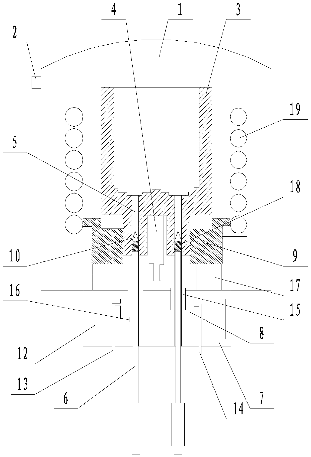
[0031] Such as Figure 1 to Figure 3 In the directional drawing and discharging type vacuum melting furnace shown, on the basis of Example 1, a groove is provided on the bottom surface of the crucible 3, and the output end of the pushing device 4 is located in the groove. The crystallization chamber 7 is surrounded by metal plates, and the crystallization chamber 7 is filled with thermal conductive silicone grease 12 . The water cooling box 8 is connected with a water inlet pipe 13 and an outlet pipe 14 , and both the water inlet pipe 13 and the water outlet pipe 14 extend to the outside of the crystallization chamber 7 . The outlet pipe 5 is covered with a silicone sleeve 15 , and the silicone sleeve 15 is fixed on the bottom of the furnace body 1 . The bottom surface of the discharge pipe 5 is flush with the bottom surface of the crystallization chamber 7 , and the discharge pipe 5 is covered with a sealing ring 16 , and the sealing ring 16 is fixedly connected with the bot...

Embodiment 3

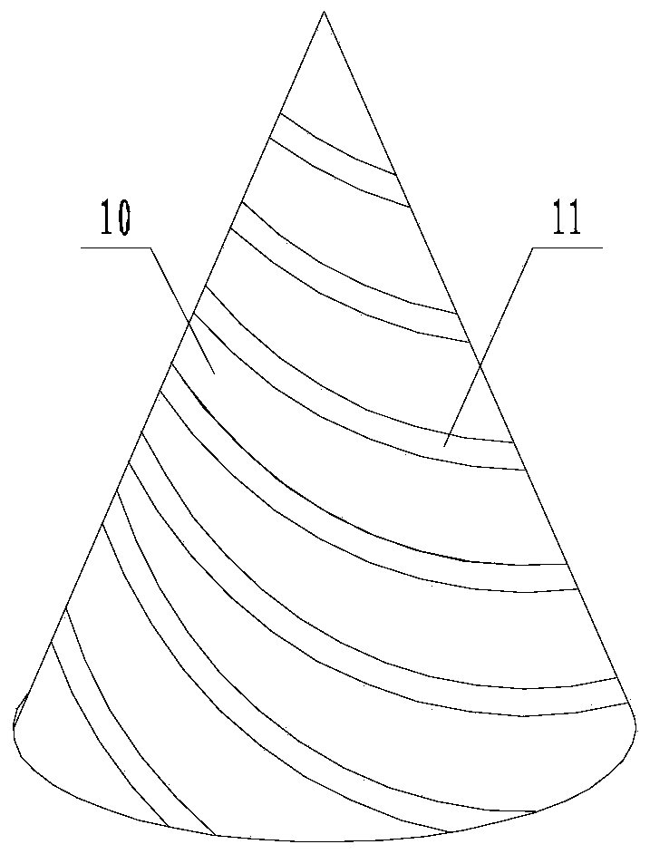
[0033] Such as Figure 1 to Figure 3 As shown in a directional drawing and discharging type vacuum melting furnace, on the basis of any of the above-mentioned embodiments, the crystallization head 10 is made of the following components by weight percentage: 20-30% iron, 8% ~10% silicon, 8%~10% rare earth minerals, 4%~6% quartz, 10%~13% copper, 2%~3% beryllium, 2%~3% titanium, 6%~ 8% of zirconium, 5% to 6% of manganese, and the rest are aluminum. The weight ratio of the quartz to the iron is 1:5.

[0034] The following table shows the control difference when the content of each component in the crystallization head is different:

[0035]

[0036] It can be seen from the above table that the thermal conductivity of the crystal head made of the components provided by the present invention is significantly lower than that of traditional alloys, which are often seventy to eighty or even hundreds. . Moreover, it can be reduced to an extremely low level after adding quartz. M...


PUM


Abstract

The invention discloses a directional drawing discharging type vacuum melting furnace. The directional drawing discharging type vacuum melting furnace comprises a furnace body with a vacuum suction port, wherein a crucible is arranged in the furnace body, induction heating coils are located outside the crucible, a pushing device with the output end facing upwards is arranged on the bottom surfaceof the interior of the furnace body, the output end of the pushing device is in contact with the bottom of the crucible, and discharge pipes penetrating through the crucible are arranged at the bottomof the crucible; drawing rods are arranged in the discharge pipes, a crystallization chamber is arranged below the furnace body, and water cooling boxes are arranged on the top surface of the interior of the crystallization chamber; the discharge pipes penetrate through the water cooling boxes, and the bottom ends of the discharge pipes penetrate through the crystallization chamber from the bottom surface of the crystallization chamber; crystallization heads are fixedly connected to the tops of the drawing rods, the crystallization heads are small upper-small and lower-big cones, and spiral grooves are formed in the surfaces of the crystallization heads; the directional drawing discharging type vacuum melting furnace further comprises isolation blocks located inside the furnace body, andthe crucible is placed on the isolation blocks. According to the directional drawing discharging type vacuum melting furnace, the problem that industrial silicon often needs secondary molding in use in the prior art is solved, and the purposes that one molding is carried out, secondary molding is not required, and the cost is reduced are realized.

Description

technical field [0001] The invention relates to the field of vacuum melting furnaces, in particular to a directional drawing and discharging vacuum melting furnace. Background technique [0002] Vacuum smelting refers to a special smelting technology that smelts under vacuum conditions. It mainly includes vacuum induction melting, vacuum arc remelting and electron beam melting. With the rapid development of modern science and technology, especially with the rapid progress of aerospace, ocean development, energy development and electronic industry, there are higher and higher requirements for the variety, output and especially quality of metal materials or non-metal materials . Vacuum smelting needs to be carried out in a vacuum smelting furnace. For the smelting of industrial silicon, castings are obtained by casting in molds after smelting. However, this method cannot directly obtain profiles and can only meet the needs of existing silicon bricks. In the production of sp...

Claims


Application Information

Patent Timeline
Patent Type & Authority Patents(China)
IPC IPC(8): F27B14/04F27B14/06F27B14/18F27D3/14C01B33/02
CPCC01B33/02F27B14/04F27B14/061F27B14/0806F27B2014/045F27B2014/0818F27D3/145
Inventor 羊实庹开正
Owner 江苏斯力康科技有限公司
Why Eureka
Try Eureka