
Passive optical network link monitoring system and method based on tunable laser

A technology for tuning lasers and passive optical networks, applied in the field of passive optical network link monitoring systems, can solve problems such as increasing the complexity of link identification algorithms, unfavorable monitoring user expansion, and affecting link state identification, etc., to achieve easy batch Effects of customization, reduction of the number of light sources, and reduction of system cost

Pending Publication Date: 2019-04-02
SOUTHEAST UNIV
View PDF0 Cites 4 Cited by
  • Summary
  • Abstract
  • Description
  • Claims
  • Application Information

AI Technical Summary

Problems solved by technology

For different monitoring user scales, this type of solution needs to design different monitoring systems, replace the light source module, receiver module and arrayed waveguide grating, which is not conducive to the expansion of monitoring users
In addition, fiber grating is a temperature-sensitive device. The temperature of the external environment of the fiber grating encoder varies widely. The center wavelength shift between the fiber grating and the light source will affect the identification of the link status and increase the complexity of the link identification algorithm.

Method used


Image

  • Passive optical network link monitoring system and method based on tunable laser
  • Passive optical network link monitoring system and method based on tunable laser
  • Passive optical network link monitoring system and method based on tunable laser

Examples


Embodiment Construction

[0028] The technical solutions of the present invention will be described in detail below in conjunction with the accompanying drawings.

[0029] figure 1 Schematic diagram of a passive optical network link monitoring system based on tunable lasers designed for the present invention, including monitoring servers, tunable lasers, three-port circulators, wavelength division multiplexers, fiber grating encoders, optical receivers and data acquisition Card. The specific functions of each component are as follows:

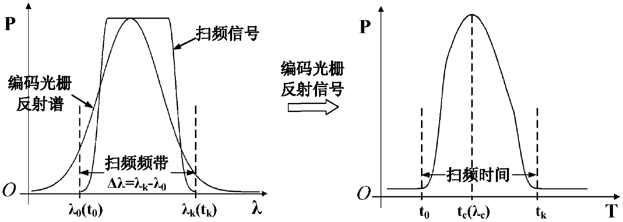
[0030] Monitoring server: including light source control port, gain control port and state identification port. The control port of the light source is connected to the tunable laser to configure the laser parameters, set the sweep frequency band, sweep rate, sweep cycle, etc. The gain control port is connected to the optical receiver to control the gain of the output signal of the optical receiver, and set the corresponding amplification factor according to the refl...


PUM


Abstract

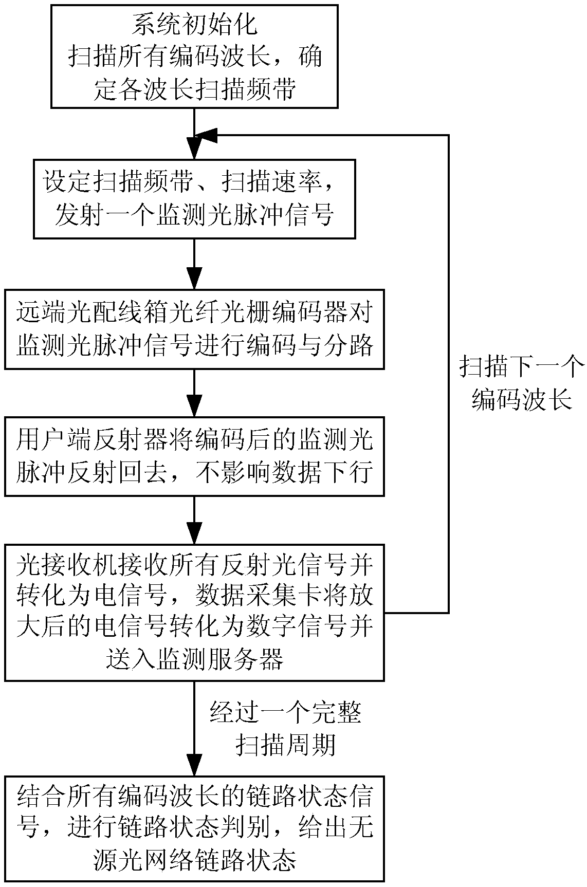
The invention discloses a passive optical network link monitoring system and method based on a tunable laser. The system comprises a monitoring server, a tunable laser, a three-port circulator, a wavelength division multiplexer, a fiber grating encoder, an optical receiver and a data acquisition card. The system scans coded wavelengths one by one by adopting the tunable laser at the transmitting end, receives reflected signals of the coded wavelengths in turn by using the single-channel optical receiver at the receiving end, and finally judges the link state of a passive optical network according to the reflected signals of all coded wavelengths, thereby overcoming the defects that the cost is high, it is not conducive to monitoring the capacity expansion of users and that the central wavelength of a fiber grating is affected by the temperature in the prior art.

Description

technical field [0001] The invention belongs to the technical field of optical fiber communication, and in particular relates to a passive optical network link monitoring system and method based on tunable lasers. Background technique [0002] Passive Optical Network (PON) has become the best solution for access network due to its service transparency, unlimited bandwidth, easy upgrade and expansion, low cost and easy maintenance. With the development of PON technology, especially the formulation of NG-PON2 related standard G.989.3, higher requirements are put forward for the security and reliability of next-generation PON. PON carries more and more new services, such as big data, cloud computing, VR / AR and other services. Once the optical network fails, it will inevitably reduce user satisfaction and even cause economic losses to users. Therefore, the real-time monitoring of optical network link faults, as a means of discovering network faults in time, has received more an...

Claims


Application Information

Patent Timeline
IPC IPC(8): H04B10/077H04B10/50H04B10/516H04B10/66
CPCH04B10/077H04B10/0773H04B10/503H04B10/516H04B10/66
Inventor 孙小菡戈志群叶晓凯樊鹤红郭浩刘朋朋李超张志选李双喜施泽楠
Owner SOUTHEAST UNIV
Learn More