Ablative pulse plasma thruster based on multi-anode electrode structure

A technology of pulsed plasma and electrode structure, applied in the direction of using plasma, thrust reverser, machine/engine, etc., can solve the problem of plasma that cannot effectively leave the nozzle, the magnetic field strength at the upper end of the magnetic nozzle increases, and the magnetic field increases in volume And other issues

Active Publication Date: 2019-04-05
BEIJING JIAOTONG UNIV
View PDF3 Cites 4 Cited by
  • Summary
  • Abstract
  • Description
  • Claims
  • Application Information

AI Technical Summary

Problems solved by technology

Hu studied the propulsion effect of thrusters with magnetic rings of different diameters and found that the strength of the magnetic field will affect the utilization of the working fluid
Takahashi measured the axial magnetic field generated by the plasma flow in the diffused magnetic nozzle, and detected that the axial magnetic field strength decreased near the nozzle, but the magnetic field strength increased at the upper end of the magnetic nozzle.
However, the magnetic field generated by permanent magnets or external circuits will increase the volume, mass and complexity, which is not conducive to its application in ablative pulsed plasma thrusters
[0005] Therefore, it is necessary to design an ablative pulsed plasma thruster with a multi-anode approach that can redirect the current path to form plasma confinement outside the nozzle and achieve highly pinched plasma without using any external measures. Jet flow, to solve the problem that the traditional Z-pinch cannot effectively act on the plasma leaving the nozzle, and the problem of mass and volume increase caused by the external magnetic field

Method used


Image

  • Ablative pulse plasma thruster based on multi-anode electrode structure
  • Ablative pulse plasma thruster based on multi-anode electrode structure
  • Ablative pulse plasma thruster based on multi-anode electrode structure

Examples


Embodiment 1

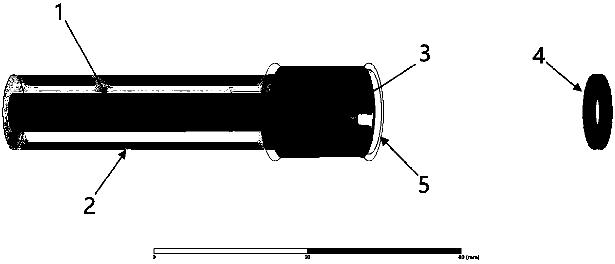
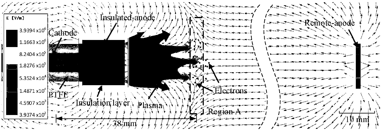
[0065] The embodiment of the present invention provides an ablation-type pulsed plasma thruster based on a multi-anode electrode structure, which adopts a coaxial electrode structure, uses two anodes to respectively realize the triggering of surface discharge and the conduction of the circuit, and realizes the process of plasma propagation in full bondage.

[0066] The embodiment of the present invention adopts the triggering mechanism of the three-junction point of the cathode to induce creeping discharge between the cathode and the anode. The separation of the electrodes and the insulating medium will lead to the interruption of the creepage path; the large distance between the electrodes will cause the decrease of the electric field strength of the cathode triple junction, making it difficult to emit initial electrons; before the arc current is formed, it is difficult to form enough plasma The body connects the cathode and anode. But as long as the strong electric field at...

Embodiment 2

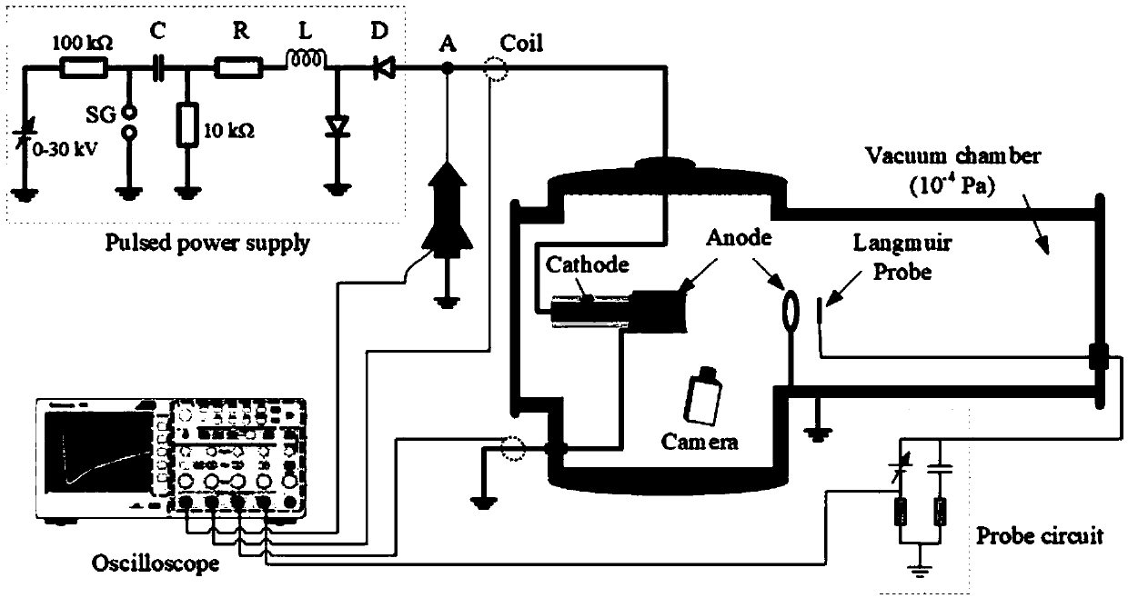
[0098] This embodiment provides an experimental system of an ablation-type pulsed plasma thruster based on a multi-anode electrode structure, and the realization structure of the experimental system is as follows image 3 As shown, the specific contents may include the following:

[0099] An application system of a vacuum metal arc thruster based on a multi-anode structure provided in this embodiment includes: a pulse power supply, a vacuum discharge device and a diagnosis system.

[0100] Pulse power supplies use energy storage capacitors as the energy source for discharge. Before discharging, the energy storage capacitor C is charged to a specific voltage, and then the ball gap switch SG is turned on through a pulse signal; at this time, the voltage of the energy storage capacitor C starts to be applied to both ends of the electrodes through the current limiting resistor R and the inductor L. Therefore, a discharge occurs due to breakdown of the vacuum gap. The diode D in ...

Embodiment 3

[0131] This embodiment provides a method for optimizing the plasma plume for an ablation-type pulsed plasma thruster based on a multi-anode electrode structure, specifically as follows:

[0132] Firstly, a method to form θ-pinch in multi-anode electrode structure APPT basically by rational arrangement is proposed. Such as Figure 16 As shown, a helical coil is placed outside the PTFE tube, the left side of the coil is connected to the cathode, and the right side is connected to the pulse power supply. when current i θ When flowing out of the helical coil, the surface of the plasma column will induce an induced current in the θ direction At the same time, the current i θ generated magnetic field is the Z-axis direction. A radial pinch force is generated on the surface of the plasma column, confining the plasma toward the center. This theta pinch is unique compared to the application of an external magnetic field in that it is formed by its own discharge current. There...


PUM


Abstract

The embodiment of the invention provides an ablative pulse plasma thruster based on a multi-anode electrode structure. The ablative pulse plasma thruster comprises a cathode, a multi-anode structure and an insulation part, wherein the cathode is externally connected to a negative high voltage, and the multi-anode structure is connected to the ground. The cathode is of a cylindrical structure, a strong electric field is formed at the junction between three sides of the cathode, field emission is induced, so that initial electrons bombard the insulation part and desorbed gas molecules, and a plasma penetrating a vacuum gap is generated to form a vacuum arc; the multi-anode structure comprises a first anode and a second anode, the first anode is in a nozzle shape, and is used for maintainingthe electric field intensity at the three joint points of the cathode; the second anode is in a ring shape and is arranged at a preset distance from the cathode structure at a preset distance, so thatthe discharging process is completed; and the insulation part is in a cylindrical shape, wraps the outer part of the cathode, is embedded into the first anode, is used for providing a raw material for generating plasma, and is used for conducting insulation and mechanical fixation on the cathode and the first anode. According to the ablative pulse plasma thruster, the full constraint of the plasma propagation process can be realized.

Description

technical field [0001] The invention relates to the technical field of micro-satellite thrusters, in particular to an ablation pulse plasma thruster based on a multi-anode electrode structure. Background technique [0002] APPT (Ablative Pulse Plasma Thruster) has a simple structure, small size and high reliability, and is one of the promising electric thrusters. In recent years, the rapid development of microsatellites has put forward higher requirements for the propulsion effect of APPT. However, the bipolar diffusion of charged particles in the plasma plume has a greater impact on the propulsion effect of the thruster. In fact, beam divergence has become one of the unfavorable characteristics of ablative pulsed plasma thrusters. Therefore, optimizing the plasma plume to increase its density plays a key role in improving the propulsion effect of ablative pulsed plasma thrusters. [0003] In the process of plasma research, Z-pinch is an important plasma confinement metho...

Claims


Application Information

Patent Timeline
Patent Type & Authority Applications(China)
IPC IPC(8): F03H1/00
CPCF03H1/0006F03H1/0087
Inventor 崔伟胜刘文正高永杰
Owner BEIJING JIAOTONG UNIV
Why Eureka
Try Eureka