Eureka AIR delivers breakthrough ideas for toughest innovation challenges, trusted by R&D personnel around the world.

Speed sensorless control method for motor with high precision and speed requirements

A technology without speed sensor and control method, which is applied in the direction of motor generator control, AC motor control, electronic commutation motor control, etc., can solve the problems of inability to estimate the motor running state accurately in real time, and inability to achieve high-precision and stable control. Achieve the effect of reducing chattering and improving speed control accuracy

Inactive Publication Date: 2019-04-09
QINGDAO UNIV
View PDF4 Cites 6 Cited by
  • Summary
  • Abstract
  • Description
  • Claims
  • Application Information

AI Technical Summary

Problems solved by technology

[0003] The general method of sensorless control is to use a speed sensorless model predictive torque control. Based on the model reference adaptive technology combined with the model predictive control strategy, an observer is designed to accurately estimate the rotor speed and reduce torque and stator flux fluctuations. Improve the dynamic and static response characteristics of the system; in addition, the use of speed observers or flux observers to increase state variables can also improve system stability. These two methods can achieve precise control when the motor is running stably, but in When the motor is just started or the running state changes, the above two methods cannot accurately estimate the running state of the motor in real time, and cannot achieve high-precision and stable control

Method used

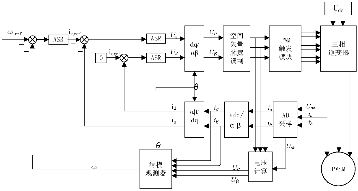
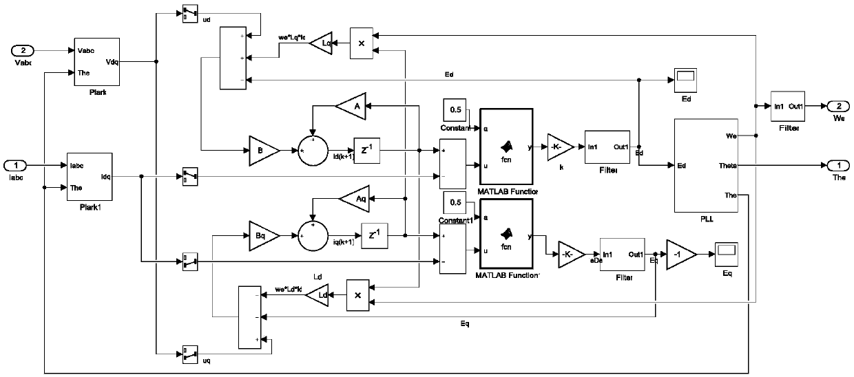
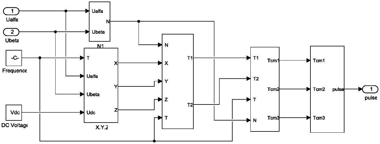

Image

  • Speed sensorless control method for motor with high precision and speed requirements
  • Speed sensorless control method for motor with high precision and speed requirements
  • Speed sensorless control method for motor with high precision and speed requirements

Examples


Embodiment

[0049] The permanent magnet synchronous motor control system described in this embodiment usually adopts a double closed-loop control structure of speed and current, and the outer loop speed tracking controller is designed based on the method of continuous time system, so that the actual output speed of the motor can track a given speed value. The specific process is as follows:

[0050] (1) Establish the mathematical model of the PMSM control system. According to the rotor magnetic field orientation theory, the mathematical model of the PMSM in the d-q axis synchronous rotating coordinate system can be expressed as:

[0051]

[0052] In the formula: L d and L q are the stator inductance in the dq synchronous rotating coordinate system, i d , i q , u d , u q are the stator current and voltage in the dq coordinate system, R s is the stator resistance, np is the number of pole pairs, ω is the mechanical angular velocity of the rotor, Φ is the flux linkage generated by th...


PUM


Abstract

The invention belongs to the technical field of motor speed control and relates to a speed sensorless control method for a motor with high precision and speed requirements. The speed sensorless control method comprises the steps of constructing a speed observer model by using an MRAS (Model Reference Adaptive System) principle; in order to utilize an SMC (Sliding Mode Control)-MRAS rotation speedidentification method, selecting a PMSM (Permanent Magnet Synchronous Motor) as a reference model and a stator current model as an adjustable model, and constructing a sliding mode surface S by usingoutput differences of the two models to improve the speed observation precision; meanwhile, replacing the conventional Sgn function with a Sigmoid function as a switching function in sliding mode control to establish a sliding mode observer model so that the system has better dynamic and static stability; then proving that the rotation speed observation method in combination with the MRAS and theSMC has strong robustness and good dynamic and static performance in the PMSM speed sensorless direct torque control system by changing the reference speed value and the load torque through operationsimulation of a Matlab / Simulink.

Description

Technical field: [0001] The invention belongs to the technical field of motor speed control, and relates to a speed sensorless control method for a motor requiring high-precision speed, in particular to the speed sensorless control of a permanent magnet synchronous motor (PMSM). Background technique [0002] The permanent magnet synchronous motor uses permanent magnets as the rotor to provide a rotating magnetic field without external excitation, and can obtain extremely high power density and torque / inertia. Permanent magnet synchronous motor has the advantages of low heat generation, simple structure, small volume and low noise, and has been widely used in small and medium-sized motion control systems, becoming an important field of research and application. The precise control of the permanent magnet synchronous motor needs to provide accurate rotor position and speed. Traditional rotor information collection is mostly through speed sensors, photoelectric encoders, resolv...

Claims


Application Information

Patent Timeline
Patent Type & Authority Applications(China)
IPC IPC(8): H02P21/24H02P21/18H02P6/34H02P25/026H02P27/06
CPCH02P21/0007H02P25/026H02P27/06H02P6/34H02P21/18H02P21/24
Inventor 兰勇夏国廷周艳婷王凯
Owner QINGDAO UNIV
Why Eureka
Eureka Blog
Learn More